17
E
n
g
li
sh
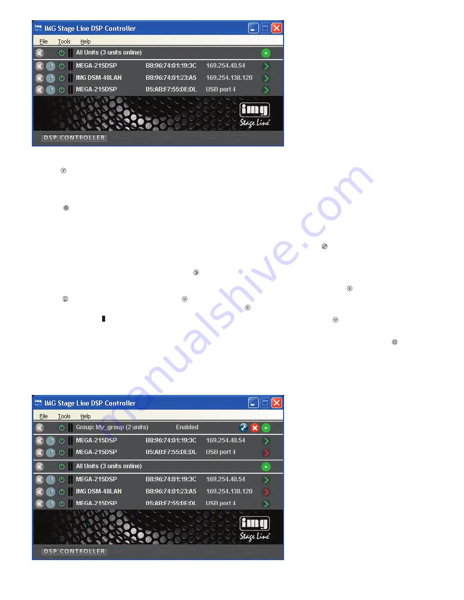
7.3.1.1 Creating a new group
1) To create a new group, call up the menu
item “Tools
±
New Group”.
2) A new window will be displayed. In the
field “Enter the name of the new group:”,
enter the group name desired.
A new row for the group will be added
to the list (row “Group: …”,
fig. 5).
3) To create or change a group, use the
button . It is possible to add or remove
units, and the group name and the link-
age characteristics can be changed.
The row “Group: …” indicates the cur-
rent number of group members (… units).
4) Use the button
at the end of the row
“Group …” to show a list of all group
members directly beneath the row
“Group …”. To hide the list again, click
the button .
7.3.1.2 Deleting a group
To delete a group, click the button
in the
corresponding row (
fig. 5). A confirma-
tion box will appear, asking you to confirm
the deletion. If units are currently contained
in the group, another confirmation box will
appear.
2. Button
to identify a unit
When this button is clicked, the button
and all LEDs at the unit will flash for a
few seconds.
3. Symbol
for the operating mode of the
unit
When the unit is in operation, the
symbol will be green; when the unit is in
the standby mode, the symbol will be
red. Click the symbol to change the
mode of the unit. The symbol will be
grey when the connection is interrupted.
When a unit is switched on and a new
connection is being established, an
additional row (“Startup …”) with the
symbol
will temporarily appear at the
end of the list.
4. The two vertical bars
are simple level
indicators for the input and the output of
the unit.
5. Indication of the unit name
For easier distinction of the same
units, the predefined name can be
changed here or in the configuration
window (
chapter 8.2,
).
6. Indication of the hardware address
(MAC address) of the network interface
or USB interface of the unit
With this address, a unit can always
be clearly identified.
7. Indication of the IP address of a unit
connected via a network
For units connected via USB, the
number of the USB interface will be indi-
cated. When the connection is inter-
rupted, “Offline” will be shown here.
8. Button
to call up the configuration
window (fig. 7) for a unit that is “online”
To hide the list of units, click the but-
ton
in the row “All units”. To show the
list again, click the button .
7.3.1 Unit groups
Multiple units may be grouped so that they
can be jointly controlled (e. g. jointly muted).
The group settings allow the definition of
the parameters that are to be jointly con-
trolled. It is always possible to add units to
the group or remove units from the group.
④
Overview window
⑤
Overview window with group


