background image

Stage Line

R

12

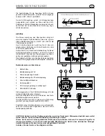
A professional audio mixing console with 100 mm HQ-faders and external special power supply. Built into a stable
flight case it is ideal especially for stage applications.  
Latest electronic technology ensures extremely low noise levels and great reliability.
Although it is neither complicated to install nor difficult to operate this device, a few minutes of your time are
required to read this manual for becoming familiar with the various features and how to use them.
Please take great care when unpacking the console. Do not discard the carton and other packing materials. They
might be needed for transport if it ever becomes necessary to return the device for service.
Never place the unit near radiators or in front of heating vents. Do not expose it to direct sunlight, excessive
humidity or dust to avoid early damage.

Features:

12 / 16 / 20 Input Channels *...................

Electronically balanced, switchable MIC / LINE, with gain control, 
subsonic filter, phantom supply with central switch (MIC-inputs),
3-way equalizer, bass / mids semiparametric,
4 AUX  controls, arranged as 2xPRE- / 2xPOST fader  sends,
routing switches to the stereo-and / or mono-groups,
PFL switch (headphones monitoring and VU-display of the channel signal),
PANPOT for the stereo outputs L-R,
PEAK LED for signal monitoring,
pre-fader insert in every channel.

4 Stereo-AUX-Inputs   .............................

Unbalanced, with gain control, switchable to the stereo-sum,
useful as line-inputs or effect-returns, two inputs with slope control.

1 STEREO Output...................................

Unbalanced, with individual L-R faders and pre-fader insert jacks, 
low  impedance outputs with hum compensation.

1 MONO Output ......................................

Unbalanced, including hum cancelling circuit, pre-fader insert jack, 
low output impedance, composed of the stereo sum L-R or  of the 
individual channels 1-16.

4 AUX Outputs ........................................

Unbalanced, with level  controls, routing- and AFL-switches.

1 RECORD Output..................................

Parallel to the L/R output, but with reduced signal level (-10 dB).

1 Stereo-Headphones Output  ................

Provided for monitoring of the individual channels (PFL) or the 
output groups L-R, MONO, AUX1-4 (AFL).

Level Indication .......................................

2x16 step LED bargraphs for indication of the group signals L-R or 
MONO, automatic switching over to display the PFL / AFL signals 
on the right bargraph.

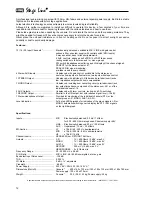
Specifications:

Inputs ......................................................

MIC

: Electronically balanced, 0.3 mV / 1kOhm,

for 200 - 600 Ohm microphones, Phantom 48V

LINE

: Electronically balanced, 20 mV / 20 kOhms

AUX

: Unbalanced, 75 mV / 20 kOhms

EQ-Section..............................................

LF

: ±15 dB / 40 - 400 Hz, semiparametric

MID

: ±15 dB / 250 Hz - 8 kHz, semiparametric

HF

: ±15 dB / 15 kHz

Channel Inserts .......................................

SEND 600 Ohm, RETURN 10 kOhms

Outputs....................................................

L-R

: 1 V / 600 Ohms / 0 dBV, max 9 V

MONO

:  1 V / 600 Ohms / 0 dBV, max 9 V

AUX1-4

: 1 V / 600 Ohms / 0 dBV, max 9 V

RECORD

: 300 mV (-10 dB), max 3 V

HEADPHONES : 2 x 8 Ohms min.

Frequency Range....................................

20 - 25 000 Hz, ± 0.5 dB

S / N Ratio...............................................

MIC / LINE : 68 / 80 dB unweighted, at max. gain

Equivalent Input Noise Level...................

-126 dB

THD.........................................................

0.025 %

VU-Meter.................................................

0 dB = 1 V, adjustable

Crosstalk .................................................

- 66 dB

Power Supply ..........................................

230 V AC / 50 Hz, 35 / 55 / 60 VA *

Dimensions (WxHxD)..............................

Console *

: 600 x 165 x 735 mm/ 740 x 165 x 735 mm/ 900 x 180 x 790 mm

Power supply : 120 x 90 x 270 mm

Weight .....................................................

Console*

: 20.5 / 25.5 / 33 kg; Power supply: 3.5 kg

Specifications are subject to change without prior notice and are according to the manufacturer.   * MMX-1221 / -1621 / -2021

Summary of Contents for MMX-1221

Page 1: ...ANLEITUNG INSTRUCTION MANUAL M O D E D E M P L O I ISTRUZIONI PER L USO Bitte vor Gebrauch lesen Please read before using A l i r e s v p a v a n t première utilisation Leggere prima dell uso MMX 1221 Best Nr 20 0460 MMX 2021 Best Nr 20 0450 MMX 1621 Best Nr 20 0510 ...

Page 2: ... Slope verwendbar als LINE Eingänge oder als Effect Returns 1 Stereo Summe Asymmetrisch niederohmig mit Brummkompensation L R einzeln regelbar Einschleif Klinkenbuchsen vor den Fadern 1 Mono Summe Asymmetrisch niederohmig mit Brummkompensation Einschleif Klinkenbuchse vor dem Fader abmischbar aus den Kanälen 1 16 oder aus der Stereosumme 4 AUX Ausgänge Asymmetrisch mit Brummkompensation regelbar R...

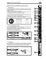
Page 3: ...n symmetrischen dynamischen Mikrofonen an phantomge speisten Eingängen ist jedoch in der Regel problemlos möglich 2 Einschleif Klinkenbuchse INSERT Hinter den Eingangsverstärkern ist in jedem Kanalzug ein Einschleifpunkt für den Anschluß von Effektgeräten Limitern etc angeordnet Das Kanalsignal wird über die Insert Klinkenbuchse ausgekoppelt und über die gleiche Buchse auch wieder zurückgeführt Da...

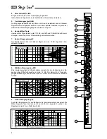
Page 4: ...m störungen können mit einer Filterschaltung unterdrückt werden 7 Höhen Klangregelung HF Der Hochtonbereich kann mit diesem Regler um max 15 dB angehoben bzw abgesenkt werden 8 Mittelton Klangregelung MID Eine semiparametrische Filterschaltung ermöglicht eine Anhebung oder Ab senkung des Mitteltonbereichs um max 15 dB Der Bereich der Frequenz gangbeeinflussung kann zwischen 250 Hz und 8 kHz stufen...

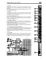
Page 5: ...tigung der PFL Taste wird der Kanal auf den Kopfhörerverstärker ge schaltet und kann vorgehört werden Gleichzeitig wird der Kanalpegel auf dem rechten LED VU Meter angezeigt Bei gedrückter PFL Taste leuchtet die darunterliegende LED auf Ist die PFL Funktion nicht angewählt so dient diese LED als PEAK Anzeige zur Aussteuerungskontrolle des Kanals 14 Ausgangssummen Wahlschalter MONO L R Tasten zur A...

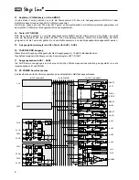
Page 6: ...ine Quellen wie CD Spieler oder Tape Recorder Stereogeräte werden an die Buchsen LEFT und RIGHT des jeweiligen Returns angeschlossen Der Anschluß von Monogeräten erfolgt über die Buchse LEFT das Signal wird dann automatisch auf beide Stereokanäle L R verteilt 4 Stereo LED Pegelanzeige Die beiden 16fach LED VU Meter können mit den Tasten 13 auf die Ausgangssummen L R oder auf die Ausgangssumme MONO...

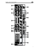
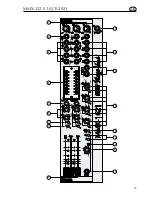
Page 7: ...7 MMX 1221 1621 2021 MASTER MASTER 1 2 3 4 5 6 7 8 9 11 12 13 14 15 16 17 18 10 D ...

Page 8: ...Mitte geeignet ist Ist die Taste nicht gedrückt so kann die Monosumme aus den Eingangskanälen abgemischt werden 15 Ausgangs Summenregler und AFL Tasten für AUX1 AUX4 16 TAPE RECORD Ausgang Stereo Record Ausgang mit abgeschwächtem Ausgangspegel 10 dB für Bandaufnahmen Das Aufnahmesignal ist abhängig von den Summenreglern LEFT RIGHT 17 Ausgangsbuchsen AUX1 AUX4 Die AUX Summenausgänge sind mit einer ...

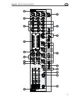
Page 9: ...9 MMX 1221 1621 2021 MASTER MASTER 1 2 3 4 5 6 7 8 9 11 12 13 14 15 16 17 18 10 D ...

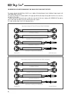
Page 10: ...anzen 600 Ohm Um jedoch die Vorteile der störkompensierten Ausgänge zu nutzen sollten unbedingt zweiadrige Leitungen mit Schirm verwendet werden damit die Signalmasse bis zum nachfolgenden Gerät separat vom Schirm geführt werden kann Beim Auftreten von Brummschleifen zwischen verschiedenen angeschlossenen Geräten sollten Kabel verwendet werden deren Schirm nur im Steckverbinder zum Mixer angeschlo...

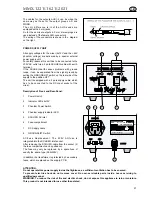
Page 11: ... Phantomspeisungs Schalter 4 Betriebsanzeige der Phantomspeisung 5 Schuko Kaltgerätebuchse 6 Sicherungsfach 7 DC Versorgungsleitung zum Mischpult 8 GROUNDLIFT Schalter Sicherungswechsel Die 230V Netzsicherung ist in die Schuko Kaltgerätebuchse integriert Das Sicherungsfach kann nach Abziehen des Netz kabels herausgenommen werden Die Netzsicherung darf nur gegen eine Sicherung gleichenTyps ausgetau...

Page 12: ... individual L R faders and pre fader insert jacks low impedance outputs with hum compensation 1 MONO Output Unbalanced including hum cancelling circuit pre fader insert jack low output impedance composed of the stereo sum L R or of the individual channels 1 16 4 AUX Outputs Unbalanced with level controls routing and AFL switches 1 RECORD Output Parallel to the L R output but with reduced signal le...

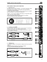
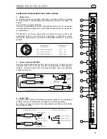
Page 13: ...ecause they might be damaged With balanced dynamic microphones there normally are no problems if they are connected to phantom powered inputs 2 Send Return Jack INSERT Behind the preamp of each input channel a send return jack 6 3 mm stereo is provided for inserting effect units limiters and similar devices The jack is used for both send and return signal For this purpose a special Y cable is requ...

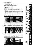
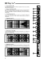
Page 14: ...below 100 Hz with a slope of 12 dB oct It can also be used to reject hum interferences 7 High Frequency Equalization This equalizer circuit allows 15 dB of boost or cut in the high frequency range with a shelving characteristic 8 Midrange Equalization This semiparametric filter circuit allows 15 dB of boost or attenuation in the midrange The center frequency of the EQ can be shifted continuously b...

Page 15: ...the main stereo image can be determined 13 PFL Switch PEAK LED If the PFL switch is depressed the channel signal can be monitored by headphones At the same time the signal level is indicated on the right LED VU meter During PFL monitoring the red LED below the PFL switch lights up If the PFL function is not used this LED works as a PEAK indicator 14 Routing Switches MONO L R These switches are pro...

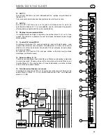
Page 16: ...ted here as well Stereo devices can be plugged to the jacks LEFT and RIGHT Mono signals have to be connected only to the input LEFT Then they are automatically routed to both stereo channels 4 LED VU Meters Two 16 step LED bargraphs for monitoring either the stereo outputs L R or the output MONO With the switches 14 the respective outputs can be selected If any of the PFL AFL switches is depressed...

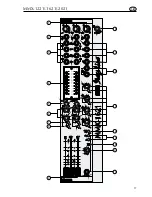
Page 17: ...17 MMX 1221 1621 2021 MASTER MASTER 1 2 3 4 5 6 7 8 9 11 12 13 14 15 16 17 18 10 GB ...

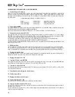
Page 18: ...rce 14 L R TO MONO Routing Switch If this switch is depressed the signals of stereo groups L R are sent to the MONO bus This way a mono signal is provided which is well suited for sound reinforcement in the center of large sound systems with a great distance between the left and right speakers 15 Output Level Controls and AFL Switches for AUX1 4 16 TAPE RECORD Output Jacks The stereo record output...

Page 19: ...19 MMX 1221 1621 2021 MASTER MASTER 1 2 3 4 5 6 7 8 9 11 12 13 14 15 16 17 18 10 GB ...

Page 20: ...input impedances 600 Ohm To ensure an effective hum compensation the signal ground should always be separate from the screen over the full length of the cables If ground loops occur between devices which are connected to the mixer cables with GROUNDLIFT should be used In this case the shield is only connected at the mixer output For further details please refer to the diagrams below ...

Page 21: ...nel 1 Power Switch 2 Indicator LEDs 2x15V 3 Phantom Power Switch 4 Phantom supply indicator LED 5 SCHUKO AC inlet 6 Fuse compartment 7 DC Supply cable 8 GROUNDLIFT Switch AC Fuse Replacement The 230V AC fuse is integrated into the SCHUKO inlet socket After removing the SCHUKO cable from the socket 5 the fuse compartment can be pulled out The fuse may only be replaced by a spare fuse of exactly the...

Page 22: ...EREO asymétrique avec circuit compensateur de ronflement réglable séparé Droite et Gauche prises JACK 6 35 avant les potentiomètres sortie basse impédance 1 sortie MONO asymétrique avec circuit compensateur de ronflement prise JACK 6 35 avant le potentiomètre sortie basse impédance réalisée à partir de la sortie STEREO D G ou directement de chaque voie 4 sorties AUX asymétriques réglables avec pos...

Page 23: ...t les endommager L utilisation de micros symétriques dynamiques sur les entrées à alimentation fantôme est en général possible 2 Prises d insertion INSERT Derrière les amplificateurs d entrée pour chaque voie il existe un point d insertion jack stéréo 6 35 pour brancher des appareils à effets spéciaux limiteurs La prise sert pour l envoi et le retour du signal nous vous conseillons d utiliser un c...

Page 24: ...signaux non souhaitées inférieures à 100 Hz avec une pente de 12 dB Octave bruits de pas par exemple ou ronflements 7 Réglage des aigus HF Vous pouvez augmenter ou diminuer les aigus de 15 dB maximum 8 Réglage des médiums MID Un circuit de filtre semi paramétrique permet d augmenter ou de diminuer les médiums de 15 dB maximum La fréquence centrale du filtre peut être réglée en continu de 250 Hz à ...

Page 25: ...pli casque vous pouvez ainsi effectuer une préécoute Simultanément le niveau du canal est affiché sur le VU mètre de droite Si la touche PFL est enfoncée la diode située en dessous s allume En revanche si la fonction PFL n est pas activée cette diode sert de diode d écrêtage contrôle du canal 14 Sélecteur Mono D G Touches pour sélectionner les sorties Mono ou Stéréo sur lesquelles le signal de la ...

Page 26: ...spectif Le branchement des appareils MONO se fait par la prise LEFT le signal est alors automatiquement partagé sur les deux canaux stéréo D G 4 Affichage stéréo Les 16 diodes du VU mètre peuvent être commutées avec les touches 13 sur les sorties D G ou la sortie MONO Si vous enfoncez une des touches PFL AFL le signal sélectionné est automatiquement affiché sur la rangée de droite La sensibilité d...

Page 27: ...27 MMX 1221 1621 2021 MASTER MASTER 1 2 3 4 5 6 7 8 9 11 12 13 14 15 16 17 18 10 F ...

Page 28: ... grandes scènes pour une sonorisation optimale lorsque la distance entre les enceintes droite et gauche est importante 15 Réglages de sortie et touches AFL pour AUX1 AUX4 16 Sorties Jack 6 35 pour enregistrement TAPE REC Sortie RECORD avec un niveau de sortie faible 10 dB pour enregistrements sur bande Le signal d enregistrement dépend des réglages de sortie DROIT GAUCHE 17 Prises de sortie AUX1 A...

Page 29: ...29 MMX 1221 1621 2021 MASTER MASTER 1 2 3 4 5 6 7 8 9 11 12 13 14 15 16 17 18 10 F ...

Page 30: ...une impédance 600 Ohms Pour profiter des avantages des sorties compensées il faut impérativement utiliser des câbles 2 conducteurs blindés afin que la masse du signal puisse être connectée séparément jusqu au prochain appareil Si des ronflements entre les divers appareils connectés apparaissent il faut utiliser des câbles avec blindage flottant le blindage n est relié qu à la sortie de la table ...

Page 31: ...nnement de l alimentation fantôme 5 Prise SCHUKO pour brancher la rallonge secteur 6 Compartiment fusibles 7 Câble d alimentation DC 8 Interrupteur GROUNDLIFT mise à la terre Remplacement des fusibles le fusible secteur 230 V est intégré dans la prise 5 Pour accéder au compartiment fusible il suffit de retirer le câble secteur Il convient de remplacer le fusible par un fusible de même type 0 5A 25...

Page 32: ...simmetrica a bassa impedenza con compensazione del ripple L R regolabili singolarmente jack di inserimento prima dei fader 1 somma mono asimmetrica a bassa impedenza con compensazione del ioneio jack di inserimento prima dei fader miscelabile dai canali 1 16 o dalla somma stereo 4 uscite AUX asimmetriche con compensazione del ripple regolabili Uscita record parallela all uscita L R ma con livello ...

Page 33: ...etrici dinamici collegati agli ingressi con alimentazione phantom non presenta generalmente nessun problema 2 Jack di inserimento INSERT Dopo gli amplificatori di ingresso ogni canale presenta un punto di inserimento per il collegamento di unità per effetti di limiter ecc Il segnale del canale viene disaccoppiato mediante la presa jack di inserimento e successivamente viene riinserito mediante la ...

Page 34: ... ecc o di ripple possono essere soppressi con questo filtro 7 Regolatore alti HF Con questo regolatore la banda alta può essere alzata o abbassata di 15 dB max 8 Regolazione medi MID Un circuito semiparametrico di filtri permette l aumento o l abbassamento di 15 dB max dei medi Il campo in cui la frequenza viene influenzata può essere spostato fra 250 Hz e 8 kHz 9 Regolazione bassi LF Anche la reg...

Page 35: ...Tasto PFL LED PEAK Se si preme il tasto PFL il canale viene collegato con il preamplificatore della cuffia pertanto è possibile il preascolto Nello stesso tempo si visualizza il livello del canale sul VU meter a LED di destra Se il tasto PFL è premuto il LED sottostante si accende Se non è selezionata la funzione PFL questa LED serve per indicare i picchi per il controllo della dinamica 14 Seletto...

Page 36: ...n la presa LEFT il segnale viene distribuito automaticamente fra i due canali stereo L R 4 Controllo a LED della dinamica stereo Con i tasti 13 i due VU meter a 16 Led possono essere commutati sulle somme di uscita L R oppurre sulla somma di uscita MONO Se è premuto uno dei tasti PFL AFL il segnale selezionato viene visualizzato automaticamente dalla catena di destra La sensibilità dei due VU mete...

Page 37: ...37 MMX 1221 1621 2021 MASTER MASTER 1 2 3 4 5 6 7 8 9 11 12 13 14 15 16 17 18 10 I ...

Page 38: ...izzare il centro Se il tasto non è premuto la somma mono può essere miscelata dai canali di ingresso 15 Regolatore delle somme di uscita e tasti AFL per AUX1 AUX4 16 Uscita TAPE RECORD Uscita stereo record con livello di uscita attenuato 10 dB per registrazioni a nastro Il segnale di registrazione dipende dai regolatori delle somme LEFT RIGHT 17 Prese di uscita AUX1 AUX4 Le uscite delle somme AUX ...

Page 39: ...39 MMX 1221 1621 2021 MASTER MASTER 1 2 3 4 5 6 7 8 9 11 12 13 14 15 16 17 18 10 I ...

Page 40: ...i con impedenze 600 ohm Per sfruttare i vantaggi delle uscite con compensazione dei disturbi si devono usare assolutamente dei cavi schermati a due conduttori per portare la massa del segnale separatamente fino all apparecchio successivo Se si presentano dei fenomeni di ripple fra diversi apparecchi collegati si dovrebbero usare dei cavi il cui schermo è collegato solo nel connettore del lato mixe...

Page 41: ...mentazione phantom 4 Spia alimentazione phantom 5 Presa per apparecchi freddi 6 Vano fusibile 7 Cavo alimentazione DC verso il mixer 8 Commutatore GROUNDLIFT Cambio fusibile Il fusibile 230 V è integrato nella presa rete Dopo aver staccato il cavo si può sfilare il vano fusibili Sostituire il fusibile soltanto con uno dello stesso tipo 0 5 A 250 V Il trasformatore di rete è protetto inoltre con 3 ...

Page 42: ...person of INTER MERCADOR GMBH CO KG In case of faulty data despite greatest diligence and its consequences the editor will neither take legal responsibility nor liability Le texte ci après y compris les illustrations et schémas est protégé par le Copyright Tous droits de traduction publication reproduction y compris d extraits informations sur microfiches et bases de données sont réservés à l édit...

Reviews: