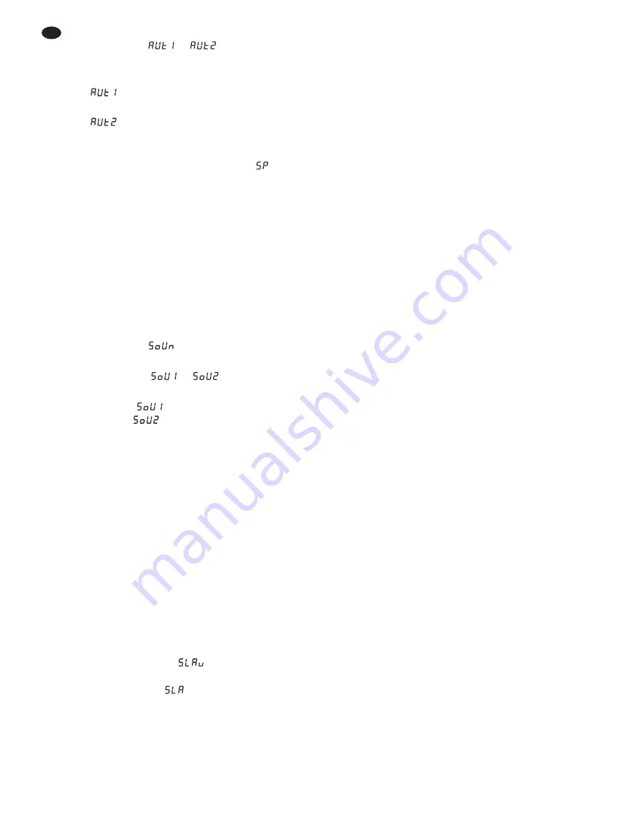
3) Press the button ENTER. The display now
switches to
or
.
4) Select the desired control program with the but-
ton
▲
or
▼
:
= crossfading and
selecting different colours
= different kinds of colour change and
stroboscope alternately
5) To change the running speed, press the button
ENTER. The display now shows
(= Speed)
and a number (1 – 9). Adjust the speed with the
button
▲
or
▼
(1 = slow, 9 = fast).
6.1.3 Music control
For music control the LEDs shortly light up at max-
imum brightness via the sound picked up by the
microphone (4).
1) Press the button MENU repeatedly until the
indication on the display does not change any
more. The display now shows the operating
mode (
fig. 1 on the very left).
2) Press the button
▲
or
▼
repeatedly until the dis-
play shows
.
3) Press the button ENTER. The display now
changes to
or
.
4) Use the button
▲
or
▼
to select white light
flashes (
) or light flashes in changing
colours (
).
6.2 Synchronous control of several
spotlights (master-slave mode)
Several PARL-40DMX can be interconnected. Then
the master unit can control all slave units in sync.
1) Interconnect the spotlights to a chain via the
DMX connections. For this purpose see chapter
6.3.1 “DMX connection”, however, skip step 1.
2) The first spotlight of the chain [whose input DMX
IN (5) is not connected] serves as a master unit
and controls the slave units. Adjust the slave
units to the slave mode:
a) Press the button MENU repeatedly until the
indication on the display does not change
any more.
b) Press the button
▲
or
▼
repeatedly until the
display shows
.
c) Press the button ENTER. The display is
switched to
.
6.3 Operation with a DMX controller
For operation via a DMX light controller (e. g. DMX-
1440 or DMX-510USB from “img Stage Line”) the
spotlight is equipped with eight DMX control chan-
nels. It is also possible to control it via 6, 5, 4 or 3
channels only as required. DMX is the abbreviation
for Digital Multiplex and means digital control of
several DMX units via a common control line. The
functions of the channels and the DMX values are
indicated in fig. 4.
6.3.1 DMX connection
For the DMX connection, the unit is provided with
3-pole XLR jacks of the following pin configuration:
pin 1 = ground, 2 = DMX-, 3 = DMX+
For connection, special cables for the DMX signal
transmission should be used (e. g. cables of the
CDMXN series from “img Stage Line”). For cable
lengths exceeding 150 m it is recommended to insert
a DMX level matching amplifier (e. g. SR-103DMX
from “img Stage Line”).
1) Connect the input DMX IN (5) to the DMX out-
put of the light controller.
2) Connect the output DMX OUT (6) to the DMX
input of the following spotlight or the following
light effect unit. Connect its output again to the
input of the following DMX unit, etc. until all
DMX-controlled units have been connected in a
chain.
3) To avoid interference in signal transmission,
for long cables or for a great number of units
connected in series, terminate the DMX output
of the last DMX unit of the chain with a 120 Ω
resistor (> 0.3 W) : Connect a corresponding ter-
minating plug (e. g. DLT-123 from “img Stage
Line”) to the DMX output jack.
12
GB


