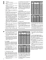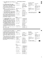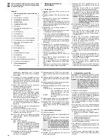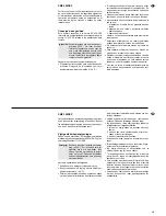
5) Die übrigen Kanäle, die ebenfalls zu hören sein
sollen, mit den zugehörigen Reglern LEVEL ent-
sprechend dazumischen.
6) Mit dem Panoramaregler PAN (5) für jeden Kanal
das Eingangssignal auf die gewünschte Stelle in
der Stereo-Basis legen.
7) Für jeden Eingangskanal getrennt die Höhen mit
dem Regler HIGH (1) und die Tiefen mit dem Reg-
ler LOW (2) bei Bedarf anheben oder absenken.
8) Den Klang für die Signalsumme [angeschlossene
Lautsprecher und Ausgang MAIN (21)] mit dem
7-Band-Graphic-Equalizer (28) optimal einstellen.
9) Die Pegelanzeige (27) zeigt den Pegel für die
Signalsumme an. Der Pegel sollte bei den laute-
sten Passagen 0 dB nicht überschreiten bzw. die
gelben LEDs „+3“ nur kurz aufleuchten. Anderen-
falls treten Signalverzerrungen auf. Dann den
Regler MAIN entsprechend zurückdrehen.
5.2
Monitorweg
Auf den Mono-Monitorweg werden die Eingangssig-
nale der Kanäle 1 – 7 gemischt, die zur Bühnenbe-
schallung benötigt werden. Als Ausgang dient die
Buchse MONITOR (20), an die über einen separa-
ten Endverstärker (siehe Kap. 4.6) Monitorlautspre-
cher angeschlossen werden.
1) Mit den Reglern MON (3) die Eingangssignale
auf den Monitorweg mischen.
2) Mit dem Regler MONITOR (29) den Pegel des
Monitorsignals einstellen.
Hinweis: Ein interner Effekt oder ein angeschlosse-
nes Effektgerät wird nicht über den Monitorweg
geführt. Der Equalizer (28) beeinflußt ebenfalls den
Monitorweg nicht.
5.3
Zumischen eines Effektes
Durch den internen digitalen Effektprozessor kann
von jedem Eingangskanal separat ein Effekt auf die
Signalsumme gemischt werden. Der interne Effekt
wird nicht auf den Ausgang MONITOR (20) geführt.
1) Den Effektprozessor mit der Taste (23) im
Bedienfeld DIGITAL PROCESSING einschalten.
Die rote LED ON neben der Taste leuchtet.
2) Mit dem Effektwahlschalter PROGRAM SELECT
(22) den gewünschten Effekt einstellen:
3) Damit der Effekt gehört werden kann, zunächst
den Regler EFFECT RTN (13) ungefähr in die
Mittelposition drehen.
4) Mit den Reglern EFF (4) für jeden Eingangskanal
den gewünschten Effektanteil einstellen, d. h.
den Pegel mit dem das Kanalsignal auf den
Effektprozessor geführt wird.
5) Mit dem Regler EFFECT RTN (13) den Gesamt-
effektpegel einstellen, der auf die Signalsumme
gemischt wird.
6) Über einen an der Buchse FOOT SW (11) ange-
schlossenen Fußschalter kann der Effekt ein-
und ausgeschaltet werden – siehe Kap. 4.9
„Fußschalter“.
5.4
Externes Effektgerät verwenden
Ist das Effektgerät über die Buchsen SEND (15) und
RETURN (16) angeschlossen, sind über den Power
Mischer keine Einstellungen möglich. Diese müssen
am Effektgerät erfolgen.
Ist das Effektgerät über die Buchsen OUT (12) und
AUX (17) angeschlossen, folgende Einstellungen
am PMX-150DSP durchführen:
1) Mit den Reglern EFF (4) für jeden Eingangskanal
den Signalanteil, der auf das Effektgerät gege-
ben werden soll, einstellen.
2) Mit dem Regler EFFECT OUT (10) den Gesamt-
pegel (Eingangssignal für das Effektgerät) ein-
stellen.
3) Das vom Effektgerät zurückgeführte Signal mit
dem Regler AUX IN (14) auf die Signalsumme
mischen.
Hinweis: Weil mit den Reglern EFF sowohl der
Signalanteil der Eingangskanäle für den internen
Effektprozessor als auch der Signalanteil für das
Effektgerät eingestellt wird, muß ggf. der interne
Effekt mit der Taste (23) ausgeschaltet oder mit dem
Regler EFFECT RTN (13) korrigiert werden.
9) The level indication (27) shows the level for the
master signal. The level should not exceed 0 dB
for music peaks or the yellow LEDs “+3” should
only shortly light up. Otherwise there will be sig-
nal distortions. Then turn back control MAIN cor-
respondingly.
5.2
Monitor way
The input signals of channels 1 to 7 which are re-
quired for stage applications are added to the mono
monitor way. Jack MONITOR (20) serves as output
to which monitor speakers are connected via a
separate power amplifier (see chapter 4.6).
1) Add the input signals to the monitor way with con-
trols MON (3).
2) Adjust the level of the monitor signal with control
MONITOR (29).
Note: An internal effect or a connected effect unit is
not directed via the monitor way. Also the equalizer
(28) does not influence the monitor way.
5.3
Adding an effect
Due to the internal digital effect processor it is possi-
ble to add an effect to the master signal separately
from each input channel. The internal effect is not
directed to the output MONITOR (20).
1) Switch on the effect processor with the button
(23) in the operating section DIGITAL PRO-
CESSING. The red LED ON next to the button
lights up.
2) Adjust the desired effect with effect selector
switch PROGRAM SELECT (22):
3) To be able to hear the effect, turn control
EFFECT RTN (13) approx. to mid-position for the
time being.
4) With controls EFF (4) adjust the desired effect
amount for each input channel, i. e. the level by
which the channel signal is directed to the effect
processor.
5) With control EFFECT RTN (13) adjust the total
effect level which is added to the master signal.
6) Via a foot switch connected to jack FOOT SW
(11) the effect can be switched on and off – see
chapter 4.9 “Foot switch”.
5.4
Using an external effect unit
If the effect unit is connected via the jacks SEND
(15) and RETURN (16), no adjustments are possible
via the power mixer. These have to be made at the
effect unit.
If the effect unit is connected via jacks OUT (12) and
AUX (17), make the following adjustments at the
PMX-150DSP:
1) With controls EFF (4) adjust for each input chan-
nel the signal amount which is to be fed to the
effect unit.
2) With control EFFECT OUT (10) adjust the total
level (input signal for the effect unit).
3) Add the signal fed back from the effect unit with
control AUX IN (14) to the master signal.
Note: as both the signal amount of the input chan-
nels for the internal effect processor and the signal
amount for the effect unit is adjusted with controls
EFF, the internal effect has to be switched off with
button (23) or be corrected with control EFFECT
RTN (13), if necessary.
5.5
Recording unit and additional unit
It is possible to monitor a recording unit connected
to jack TAPE (18), e. g. for checking the recording
via the internal power amplifier of the PMX-150DSP.
Add the signal with control TAPE IN (32) to the
master signal. To hear only the recording unit, turn
the other input controls LEVEL (6) and AUX IN (14)
to zero.
A unit connected to jack AUX (17) can be added
to the master signal with control AUX IN (14). To
hear only this unit, turn the other input controls
LEVEL (6) and TAPE IN (32) to zero.
Note: the inputs TAPE and AUX are not fed to the
monitor way.
8
GB
D
A
CH
10 Hall-Effekte
Position
Effekt
Nachhallzeit
0
kein Effekt
—
1
Cathedral
0,5 s
2
Large Hall
3,0 s
3
Mid Hall
1,7 s
4
Large Room
1,5 s
5
Small Room
0,8 s
6
Plate
1,5 s
7
Percussion
1,2 s
8
Vocal 1
3,0 s
9
Vocal 2
1,5 s
10
Vocal 3
0,9 s
5 Delay-Effekte
Position
Effekt
Delay-Zeit
links /rechts
11
Delay 1
100 / 200 ms
12
Delay 2
200 / 400 ms
13
Delay 3
300 / 600 ms
14
Delay 4
400 / 210 ms
15
Delay 5
500 / 310 ms
Feedback
links /rechts
40 / 20 %
30 / 15 %
30 / 15 %
30 / 30 %
20 / 20 %
10 Reverberation Effects
Position
Effect
Reverb. Time
0
no effect
—
1
Cathedral
0.5 s
2
Large Hall
3.0 s
3
Mid Hall
1.7 s
4
Large Room
1.5 s
5
Small Room
0.8 s
6
Plate
1.5 s
7
Percussion
1.2 s
8
Vocal 1
3.0 s
9
Vocal 2
1.5 s
10
Vocal 3
0.9 s
5 Delay-Effekte
Position
Effect
Delay Time
left / right
11
Delay 1
100 / 200 ms
12
Delay 2
200 / 400 ms
13
Delay 3
300 / 600 ms
14
Delay 4
400 / 210 ms
15
Delay 5
500 / 310 ms
Feedback
left / right
40 / 20 %
30 / 15 %
30 / 15 %
30 / 30 %
20 / 20 %


