12
English
of the compressor and the right channel of
the signal source to one of the jacks INPUT
of channel B .
2) Connect one of the jacks OUTPUT (28 or
29) of channel A of the compressor to the
left channel input of the following unit
(e . g . PA amplifier) and one of the jacks
OUTPUT of channel B to the right channel
input of the following unit .
5.3 Using the sidechain connections
The sidechain connections are used to control
the compressor by a signal processed exter-
nally or by an external signal .
For controlling the compressor by a fil-
tered signal (e . g . when used as a de-esser
to suppress sibilance,
☞
chapter 6 .6 .1), an
equalizer must be inserted into the sidechain
jacks .
1) Connect the output SIDECHAIN SEND (33)
to the input of the equalizer .
2) Connect the output of the equalizer,
where the processed signal is available,
to the input SIDECHAIN RETURN (34) .
For controlling the compressor by an external
signal (e . g . when used as a ducker where the
music will be automatically faded out during
an announcement,
☞
chapter 6 .6 .2), con-
nect the signal source to the input SIDECHAIN
RETURN (34) .
5.4 Power supply
Connect the mains cable provided to the
mains jack (26) and the plug to a mains socket
(230 V/ 50 Hz) .
6 Operation
A) When the compressor is used for pro-
cessing
two different signal sources
(e . g .
two instruments or two vocal micro-
phones), all settings for the channels A
and B must be made separately . The but-
ton DUAL MONO / CH A MASTER (25)
must not be pressed . Unless otherwise
stated, the text below will only describe
channel A; operation of channel B is iden-
tical .
B) When a
stereo signal
is processed (e . g . by
a CD player), the channels A and B must
be controlled exactly in the same way to
prevent shifts in balance . For this pur-
pose, press the button DUAL MONO / CH
A MASTER (25) . All settings will be made
via the control section of channel A (1) only
and will be effective for both channels in
the same way . Exceptions are the switches
OUT/ IN (21) for switching over the VU-
meters (10, 11) separately between the
input signals and output signals, the
switches BYPASS / COMP for bypassing the
signal processing, the sw4 dBu /
−10 dBV (30) for internal level matching
and the sidechain switches (5, 14, 16) .
The control signal is the sum of
the audio signals of the two chan-
nels . Therefore, it is important to adjust
both channels to the same rated level
+4 dBu / −10 dBV (30) .
6.1 Adjusting the
correct operating level
1) Set the 4 dBu / −10 dBV (30) on
the rear panel of the unit to +4 dBu (dis-
engage it) .
2) Switch on the unit with the POWER
switch (3) . The power LED on the switch
will light up .
3) Set the button BYPASS/COMP (23) to
BYPASS (disengage it) . The compressor will
be bridged . When it is switched off, the
compressor will also be bridged, regardless
of the switch position . After switching on
all other units or instruments connected,
they must be audible . If not, check all con-
nections .
4) Press the button OUT/ IN (21) . The VU-
meter (10, 11) will indicate the input level .
In case of overload (red LEDs permanently
on), reduce the output level on the signal
source .
If the response of the VU-meter is too
poor, press the selector switch for the rated
level (30) on the rear panel of the unit (po-
sition −10 dBV) . Thus, the signal level will
be internally increased by 11 .8 dB (4 dBu
= 1 .8 dBV) . The output level will not be
modified because the signal at the output
will be decreased accordingly . It may be
necessary to increase the input level on
the mixer or the output level on the signal
source until an optimum level control is
obtained .
An indication of 0 dB on the VU-meter
corresponds to the rated level −10 dBV or
+4 dBu selected accordingly .
6.2 Adjusting the expander / gate
An expander will behave contrary to the com-
pressor: It will boost the dynamics of an audio
signal . When used in the lower level range
(downward expander), signals below an ad-
justable level will become even fainter . This
allows systematic suppression of noise which
is lower than the wanted signal, but which
will interfere especially in pauses between
the wanted signal . Thus, it will be possible
to suppress noise, hum, crosstalk from other
channels or the undesired sound of an instru-
ment nearby when picking up sound with a
microphone . For compressing an audio sig-
nal and increasing its volume subsequently,
it is most important to attenuate the noise
with an expander; otherwise, it would also
be amplified .
The extent of signal attenuation below
the threshold is adjustable via the ratio con-
trol . An expander with an extremely adjusted
expansion ratio is a gate (= gate that will
only open to allow the wanted signal to pass
through) . As an effect, the fade-out of an
instrument can be reduced with a gate .
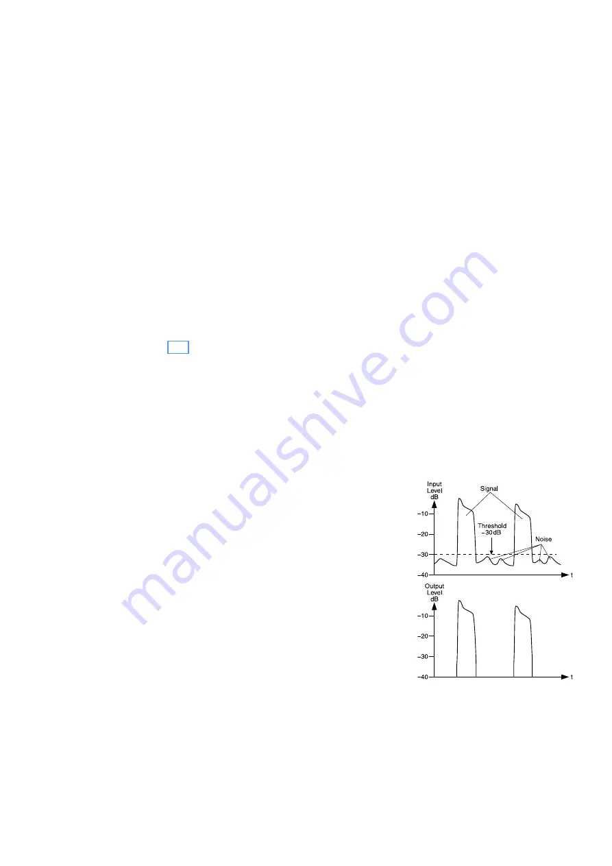
Figure 5 shows the function of a gate by
means of an input signal with a noise part
and the “cleaned” output signal .
Abb. 5
Gate at a threshold of −30 dB


