58
de
fr
en
nl
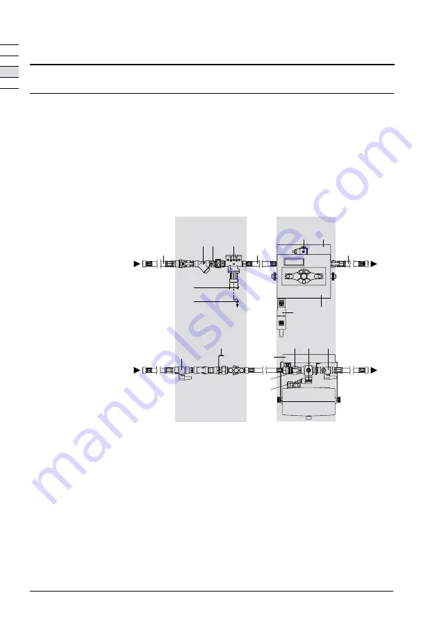
Front view
Top view
Legend
Modules A and B are fastened horizontally to a sturdy wall using the base plate (10, 11).
• Bring modules A and B with flexible hose (6) into the desired position.* Important! There must be
no kinks in the flexible hose (6).
*
There are no standard instructions for back flow preventer BA (ST). If a larger gap is required between modules
A and B, a longer flexible hose can be installed (max. length = 2000 mm, min. inside diameter = 10 mm).
• Connect modules A and B with flexible hose (6).
• Flexible hoses (5) for connecting the mains water supply and for connecting to the installation.
Module A
Module B
SNS
3
4
7.1
10
FIQ
SA
SNS
ST
9
SF
5
55
6
11
NS
1.2
1
∅
32 mm
SA
7
8
11
1 BrainCube control
1.2 Mains plug
3 SNS ball valve
4 SA ball valve
5 Flexible hose R ½ x G ½, L = 500 mm
6 Flexible hose G ¾ x G ½, L = 500 mm
7 Water make-up valve cable,
L = 2500 mm
FIQ Contact water meter
NS Water make-up valve 230 V/50
Hz
SF Strainer
ST Back flow preventer BA, EN 1717
SNS Connection to mains water supply
SA Water make-up connection for
the connected system
7.1 Water make-up valve plug
8 Cable for FIQ, L = 1050 mm,
by contractor 2 x 0.25 mm²
9 Non-return valve
10 Module A base plate with
securing strap
11 Module B base plate with
securing strap
by contractor
Installation
Installation
Summary of Contents for IMI PNEUMATEX Pleno PI
Page 1: ...WPMOIN0002 02 2019 Pleno PI...
Page 99: ......


