
F64B, F64L Ultra high efficiency coalescing filter
Installation & Maintenance Instructions
3/19
I&M/en 8.240.115.01
Our policy is one of continued research and development. We therefore reserve the right to amend,
without notice, the specifications given in this document. (1999 - I&M8076c) © 2015 IMI International s.r.o.
Technical features
Option selector
Port
2 1/4”
3 3/8“
4 1/2“
6 3/4
N
No yoke
Bowl
P
Transparent with guard
R
Metal with Pyrex sight glass
T Transparent
Thread
A
PTF (1/8 PTF gauge ports)
B
ISO Rc taper (1/8 ISO Rc gauge ports)
G
ISO G parallel (1/8 ISO Rc gauge ports)
N
No thread (basic unit)
F64
˙
–
˙˙N
–
˙˙0
Drain
A Automatic
M Manual
Type
B
Coalescing & activated
carbon element
L
Extended coalescing &
activated carbon element
Fluid: Compressed air
Maximum pressure:
Metal bowl: 17 bar (250 psig)
Transparent bowl: 10 bar (150 psig)
Operating temperature*:
Metal bowl: –20° to +65°C (0° to +150°F)
Transparent bowl: –20° to +50°C (0° to +125°F)
* Air supply must be dry enough to avoid ice
formation at temperatures below +2°C (+35°F).
Integral F64B/L Pre-filter Element: 40 μm
nominal
Particle Removal F64B/L: 0,01 μm
Maximum Remaining Oil Content:
0,003 mg/m
3
at +21°C (+70°F)
Air Quality: Within ISO 8573-1: class 1.7.1
Inlet pressure Maximum Flow dm
3
/s (scfm)*1)
bar (psig) F64B F64L
1 (14,5) 2,8 (5,9) 4,4 (9,3)
3 (43,5) 4,8 (10,2) 7,6 (16,1)
5 (72,5) 6,2 (13,1) 9,8 (20,8)
6,3 (91,4) 7,0 (14,8) 11,0 (23,3)
7 (101,5) 7,3 (15,5) 11,5 (24,4)
9 (130,5) 8,4 (17,8) 13,2 (28,0)
*1) Maximum flow to maintain stated oil removal
performance.
Automatic drain connection: 1/8”
Automatic drain operating conditions
Bowl pressure required to close drain:
Greater than 0,3 bar (5 psig)
Bowl pressure required to open drain:
Less than 0,2 bar (3 psig)
Minimum air flow required to close drain:
1 dm3/s (2 scfm)
Manual operation: Depress pin inside drain
outlet to drain bowl
Nominal bowl size: 0,2 litre (7 fluid oz)
Materials:
Body: Zinc
Bowl:
Metal: Zinc
Transparent: Polycarbonate
Guard, transparent bowl: Steel
Metal bowl sight glass, standard: Pyrex
Element: Composite materials
Elastomers: Synthetic rubber
Replacement Items
Service kit,
contains required items circled
4380-201
Pyrex sight glass
2273-97
Element, coalescing:
F64B
5350-99
F64L
5350-98
Element, integral pre-filter
3698-02
Activated carbon pack
5568-01
Manual drain
684-84
Automatic drain
3000-04
Installation
1. Install unit vertically in air line - upstream of
lubricators and cycling valves, with air flow in
direction of arrow on body, as close as
possible to the device being serviced.
2. Before assembling the basic unit into the yoke
the port seal o-rings should be lightly smeared
with o-ring grease.
3. Locate clamp ring under lugs on top of yoke,
offer basic unit into yoke with directional
arrows correctly aligned (an interference fit
prevents assembly if misaligned) before
engaging and fully tightening the clamp ring.
4. Turn bowl fully clockwise into body before
pressurizing.
5. Auto-drain units may be fitted with a short
drain pipe and connector, minimum 5 mm
bore, to the G1⁄8 bottom outlet.
6.Install a Norgren general purpose filter with a
5 μm element upstream of the oil removal filter
to obtain maximum element service life.
Operation
On exceptionally dirty lines it may be necessary
to clean the pre-filter element at 90 day intervals.
Do not exceed Maximum Flow rating or
excessive pressure drop will result or oil carry
over may occur. The top filter element acts as
absorbant pack to remove any small traces of oil
or hydro-carbon gases which might be carried
over from the lower bowl. These elements also
provide protection in the event of any failure of
the lower filter. Resistance to air flow will grad-
ually increase as the filter element collects solid
particles. The pressure differential across the
element should not be allowed to exceed
Servicing
Air Service equipment should be initially
maintained annually. Use, quality of air and
condition at examination may indicate
adjustment of the maintenance interval.
1. Open manual drain to expel accumulated
liquids. Keep liquids below element (46, 50).
2. To operate automatic drain manually, lift
operating pin in bottom outlet with a blunt rod.
3. Clean or replace filter element when dirty.
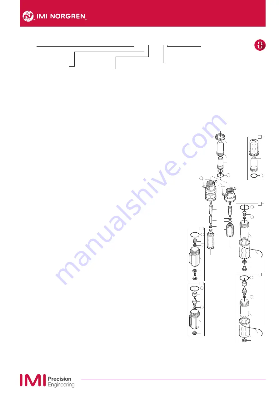
Disassembly
1. Shut off inlet pressure. Reduce pressure in
inlet and outlet lines to zero.
2. For ease of maintenance the unit can be
removed from the yoke by unscrewing the
clamp ring, which will jack the unit out
downwards.
3. To disassemble the lower filter section
unscrew the filter bowl (14, 21, 28, 37) and
remove with bowl o-ring.
4. Remove coalescing element (46, 50) by hand.
5. Remove pre-filter element (49, 54).
6. Unscrew top bowl and remove top element
(8).
7. Disassemble in general accordance with the
item numbers on exploded view. Do not
remove the drains unless replacement is
necessary. Remove and replace only if they
malfunction.
42
44
43
8
9
1
2
5
6
3
11
49
48
47
46
10
12
15
19
38
39
40
41
16
17
20
18
45
13
54
53
52
51
50
29
30
35
32
33
36
31
34
22
24
26
25
23
27
4
14
21
28
37
7
Cleaning
1. Partial cleaning of the pre-filter element (49,
54) is possible by washing the element in
soapy water and blowing out thoroughly
with compressed air. Replacement by a clean
element is recommended.The main


