
F68C, F68H Oil removal filter
Installation & Maintenance Instructions
7/15
I&M/en 8.260.105.01
Our policy is one of continued research and development. We therefore reserve the right to amend,
without notice, the specifications given in this document. (1999 - I&M8089d) © 2015 IMI International s.r.o.
Technical Data
Fluid: Compressed air
Maximum pressure: 17 bar (250 psig)
Operating temperature*:
-20° ... +65°C (0° ... +150°F)
* Air supply must be dry enough to avoid ice
formation at temperatures below +2°C (+35°F).
Partical removal: 0,01 µm
Air quality: Within ISO 8573-1, Class 1
(particulates) and Class 2 (oil content).
Maximum remaining oil content: 0,01 mg/m
3
at
+20°C (+70°F) with an inlet concentration
of 17 mg/m
3
.
Maximum flow at 6,3 bar (90 psig) inlet pressure
to maintain stated oil removal performance:
1/2” ports: 35 dm
3
/s (74 scfm)
3/4” ports: 35 dm
3
/s (74 scfm)
1” ports: 60 dm
3
/s (127 scfm)
1/4 turn manual drain connection: 1/8” pipe
thread
Automatic drain connection: 1/8” pipe thread
Automatic drain operating conditions (float
operated)
Bowl pressure required to close drain:
Greater than 0,3 bar (5 psig)
Bowl pressure required to open drain:
Less than 0,2 bar (3 psig)
Minimum air flow required to close drain:
1 dm3/s (2 scfm)
Manual operation: Depress pin inside drain
outlet to drain bowl
Nominal bowl size:
0,5 litre (1 pint U.S.)
1 litre (1 quart U.S.)
Materials:
Body: Aluminium
Yoke: Aluminium
Bowl: Aluminium
Liquid level indicator: Pyrex
Element: Synthetic fibre and polyurethane foam
Elastomers: Synthetic rubber
Service life indicator:
Body: Transparent nylon
Internal parts: Acetal
Spring: Stainless steel
Elastomers NBR
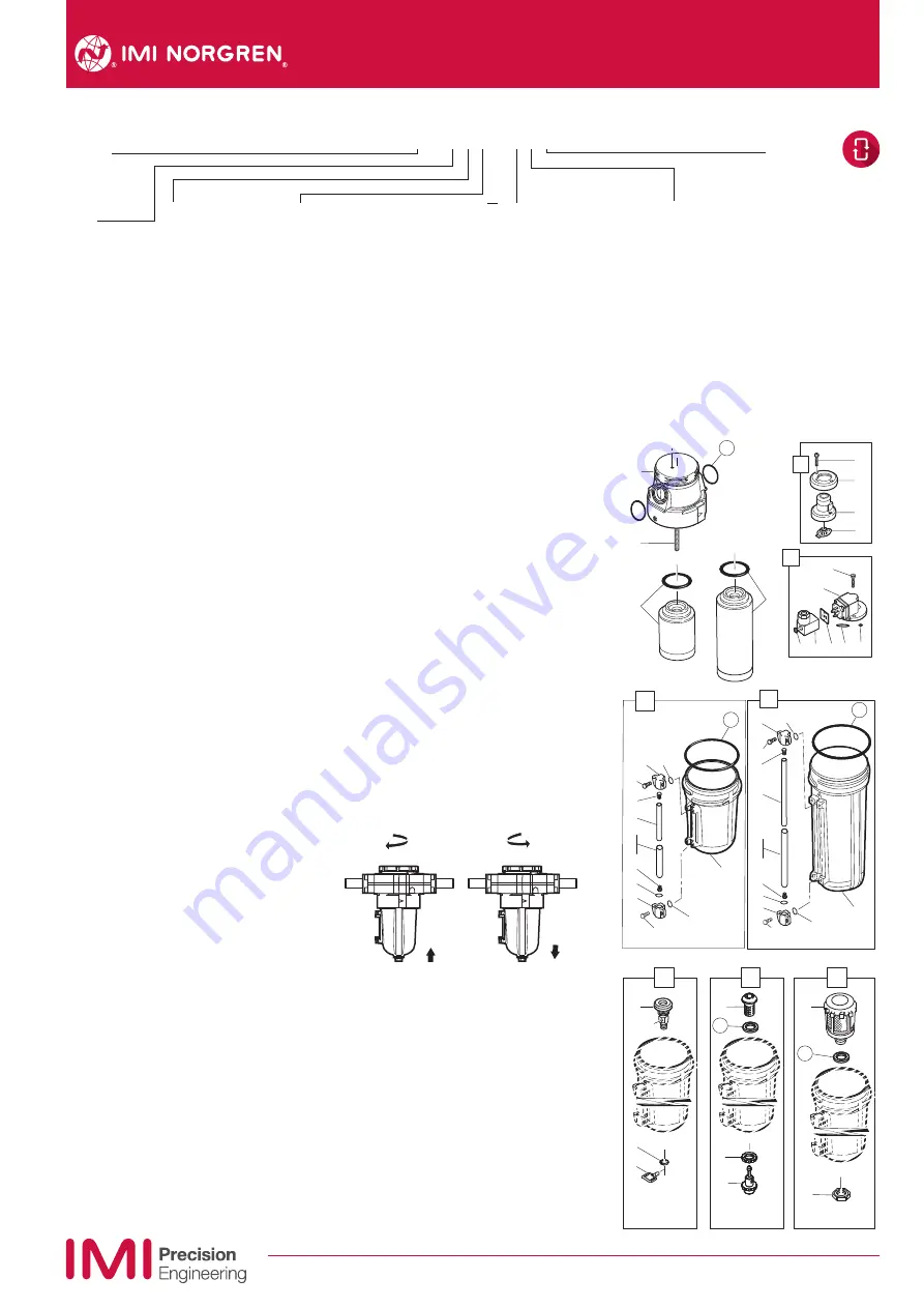
Replacement Items
Service kit
(items circled on exploded view)
4380-301
0.5 litre bowl liquid level lens (19 thru 27)
4380-060
1 litre bowl liquid level lens (30 thru 38)
4380-061
Filter element, standard, short (53) 5351-08
Filter element, high flow, long (53) 5351-03
Automatic drain, G1/8 outlet (49) 3000-97
Automatic drain, 1/8 PTF outlet (49) 3000-10
Manual drain, spindle type (44)
684-84
Manual drain, 1/4 turn (40)
619-50
Mechanical service life indicator (1) 5797-50
Electrical service life indicator (6) 4020-51R
Installation
1. Install yoke in air line -
• with air flow in direction of arrow on top of
yoke,
• upstream of regulators, lubricators, and
cycling valves,
• as close as possible to the air supply when
filter is used as a main line filter,
• as close as possible to the device being
serviced when filter is used as a final filter.
2. Connect piping to yoke ports using pipe
thread sealant on male threads only.
3. Lubricate o-rings (15) with a light coat of
o-ring grease, then place o-rings in grooves
in body (14).
4. Place clamp ring under lugs on top of yoke.
5. Make sure arrows on yoke and filter point in
same direction, then plug filter into yoke and
tighten clamp ring hand tight.
6. Turn bowl into body until arrowhead on bowl
is aligned with or to the right of the
arrowhead on the body.
7. Flexible tube with 3mm (0.125”) minimum I.D.
can be connected to the automatic drain.
Avoid restrictions in the tube.
8. Install a Norgren general purpose filter with a
5 µm element upstream of the oil removal
filter to obtain maximum element service life.
Servicing
1.Open manual drain to expel accumulated
liquids. Keep liquids below element (53).
2. Replace filter element when pressure drop
across element exceeds 0,7 bar (10 psig).
The mechanical service life indicator shows
approximately all red and the optional
electrical service life indicator provides an
electrical output when pressure drop across
the element reaches 0,7 bar (10 psig)
Diassembly
1. Shut off inlet pressure. Reduce pressure in
inlet and outlet lines to zero.
2. Unscrew the clamp ring and remove filter
from yoke.
3. Disassemble in general accordance with the
item numbers on exploded view. Do not
remove the drains
or the service indicators unless replacement
is necessary. Remove and replace only if they
malfunction. Do not attempt to remove rod
(54), as it is cemented to body.
2
5
3
4
7
10
11
12
13
15
14
1
6
8
9
53
53
54
29
32
32
31
30
36
37
35
31
30
33
39
34
33
38
18
28
19
25
26
24
21
22
19
21
20
20
23
22
27
41
43
42
40
46
45
47
44
48
51
50
49
52
Technical features
Option selector
* Only available with the F68C standard filter. ** See Norgren publication IM-900.920 for specifications and electrical wire connections of the optional electric service indicator.
Port
4* 1/2”
6 3/4“
8 1“
N
No yoke
Options
D
With mechanical service life indicator
E
With electrical service life indicator*
N
No service life indicator
Drain
A Automatic
E
Closed bottom
M
Manual, spindle type
Q
Manual, 1/4 turn
Bowl
C
1 litre (1 quart) no liquid indicator
M 0,5 litre (1 pint) no liquid indicator
R
0,5 litre (1 pint) with liquid indicator
U
1 litre (1 quart) With liquid indicator
Thread
A PTF
B
ISO Rc tapered
G
ISO G parallel
N
No yoke
Element
0 Coalescing
F68
˙
–
˙˙˙
–
˙˙˙
Bowl
C Standard
H
High flow


