background image

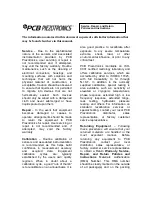
Model CS670A01

Echo® Wireless Vibration Sensor, Intrinsically Safe

Installation and Operating Manual

For assistance with the operation of this product,

contact PCB Piezotronics, Inc.

Toll-free: 800-959-4464

24-hour SensorLine: 716-684-0001

Fax: 716-684-3823

E-mail: imi@pcb.com

Web: www.imi-sensors.com

Summary of Contents for 66103PPZ2

Page 1: ... Intrinsically Safe Installation and Operating Manual For assistance with the operation of this product contact PCB Piezotronics Inc Toll free 800 959 4464 24 hour SensorLine 716 684 0001 Fax 716 684 3823 E mail imi pcb com Web www imi sensors com ...

Page 2: ...ity regimen When in doubt about a calibration cycle a good rule of thumb is to recalibrate on an annual basis It is also good practice to recalibrate after exposure to any severe temperature extreme shock load or other environmental influence or prior to any critical test PCB Piezotronics maintains an ISO 9001 certified metrology laboratory and offers calibration services which are accredited by A...

Page 3: ...urchase Order should include authorization to proceed and return at current pricing which can be obtained from a factory customer service representative Contact Information International customers should direct all inquiries to their local distributor or sales office A complete list of distributors and offices can be found at www pcb com Customers within the United States may contact their local s...

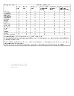
Page 4: ... O PCB板 X O O O O O 电气连接器 O O O O O O 压电晶体 X O O O O O 环氧 O O O O O O 铁氟龙 O O O O O O 电子 O O O O O O 厚膜基板 O O X O O O 电线 O O O O O O 电缆 X O O O O O 塑料 O O O O O O 焊接 X O O O O O 铜合金 黄铜 X O O O O O 本表格依据 SJ T 11364 的规定编制 O 表示该有害物质在该部件所有均质材料中的含量均在 GB T 26572 规定的限量要求以下 X 表示该有害物质至少在该部件的某一均质材料中的含量超出 GB T 26572 规定的限量要求 铅是欧洲RoHS指令2011 65 EU附件三和附件四目前由于允许的豁免 CHINA RoHS COMPLIANCE ...

Page 5: ...te O O X O O O Wires O O O O O O Cables X O O O O O Plastic O O O O O O Solder X O O O O O Copper Alloy Brass X O O O O O This table is prepared in accordance with the provisions of SJ T 11364 O Indicates that said hazardous substance contained in all of the homogeneous materials for this part is below the limit requirement of GB T 26572 X Indicates that said hazardous substance contained in at le...

Page 6: ...41967 Rev C ECO 43669 Echo Wireless Vibration Sensor User s Manual Models 670A01 RV670A01 and CS670A01 ...

Page 7: ...screen similar to the following and then click on Echo EchoPlus Sensors 8 Factory Defaults 12 Explanation of Echo Wireless Sensor Parameters 12 Parameters can be changed by using the up and down arrows or by typing the values in the appropriate box Click on the Set button by the parameter to actually program the sensor 12 Sensor ID 12 Transmission Interval 12 RVL Residual Vibration Level 12 CF Rep...

Page 8: ...communications Operation of this equipment in a residential area is likely to cause harmful interference in which case the user will be required to correct the interference at his own expense INDUSTRY CANADA IC NOTICE IC 9732A IMI670A01 Operation is subject to the following two conditions 1 this device may not cause interference and 2 this device must accept any interference including interference...

Page 9: ...The transmitted data is received by an Echo Receiver decoded and sent via Ethernet to a computer or server running the Echo Monitoring Software For additional information on the Echo Receiver and the Echo Monitoring Software please refer to their respective manuals The Model RV670A01 Echo Wireless Vibration Sensor with RV Raw Vibration Output operates identically to the standard model and addition...

Page 10: ...erial If polycarbonate is not compatible with the processes in your plant contact IMI for potential options Will Damage Polycarbonate Require Caution Considered Safe Alkali bleaches such as sodium hypochlorite Cyclohexanone Acetic acid Acetone Diesel oil Ammonium chloride Acrylonitrile Formic acid Antimony trichloride Ammonia Gasoline Borax in H2O Amyl acetate Glycerine Butane Benzene Heating oil ...

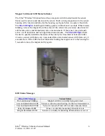
Page 11: ...ctive it will deactivate and no longer take measurements The blue LED light allows the user to quickly determine the status of the unit by the time interval between blinks An active sensor will blink every 4 seconds while a deactivated sensor will blink every 8 seconds Note If the LED does not blink after holding the magnet next to the housing for 5 seconds remove the magnet and try again LED Stat...

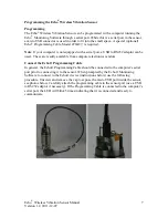
Page 12: ...ptor can be used These are readily available from computer electronics vendors Connect the Echo Programming Cable In general the Echo Programming Cable should be connected to the computer s serial port prior to connecting it to the sensor When prompted by the Echo Monitoring Software to connect to the Echo device instructions below use the following procedure Unscrew and remove the cap to expose t...

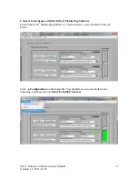
Page 13: ...nnect to the Sensor with the Echo Monitoring Software Launch the Echo Monitoring Software You should see a screen similar to the one below Click on Configuration on the menu bar You should see a screen similar to the following and then click on Echo EchoPlus Sensors ...

Page 14: ...view and Echo Sensors parameters then click on Next at the bottom of the screen Select the receiver where data from this specific sensor should be sent This also by default specifies the database where data from this sensor will be stored The default setting for a single receiver installation is shown below After the receiver is selected click on Next ...

Page 15: ...sensor and database parameters will be set to the same values Some important program information and alarms are based on theses settings See the Echo Monitoring Software User s Manual for setup details At this time we will focus on programming the Echo Sensor only Select I will only configure the Echo device at this time and click Next When the following screen is displayed make sure the Echo Prog...

Page 16: ... will appear Select the appropriate COM port and click on Link to Echo Note The Access Level is factory set and is not user selectable The green bar should illuminate indicating the connection has been made The fields to the right of the window will populate with the current programmed parameters ...

Page 17: ...terval the primary lithium thionyl chloride Li SOCl2 batteries are expected to last in excess of 5 years Note Decreasing the transmission interval i e increasing the number of measurements per day will not only reduce battery life but will also use more receiver bandwidth Thus fewer sensors can be used with a receiver See the Echo Receiver User s Manual for guidelines regarding the number of senso...

Page 18: ...ctions of the transmitted signal While this does not affect data accuracy it can use unnecessary receiver bandwidth to deal with the reflections If the received signal from a sensor is 65 dB the Transmission Power should be changed from High to Low to eliminate this problem This will cause the transmitted power to be reduced by about 45 dB Transmission Band The Echo System can operate on 12 indepe...

Page 19: ...abase a message similar to the following will be displayed Click OK For details on setting up the database see the Echo Monitoring Software User s Manual A screen similar to the following will be displayed Ignore the screen and click Finish This will be used when you set up the actual database For complete programming options see the Echo Monitoring Software User s Manual ...

Page 20: ...signal directly from the embedded accelerometer The cable converts the standard constant current sensor power provided by most data collectors to the low voltage supply required by the Echo Sensor To make raw vibration measurements remove the shorting cap on the RV output connector Attach the 4 pin connector on the cable to the RV output connector Connect the BNC end to a data collector and set se...

Page 21: ...et due to the size and mass of the sensor The correct mounting torque for the sensor is 3 to 5 ft lb 4 to 7 N m It is also a good idea to put a small amount of silicon grease on the bottom of the sensor before mounting WARNING Do NOT tighten the sensor by twisting on the housing Damage to the sensor WILL occur Tighten to the correct torque using a wrench on the hex base Outline Drawing See enclose...

Page 22: ...l 080A127 1 spot face tool shown below This tool will prepare a flat surface and drill the appropriate pilot hole for a 28 UNF thread A 28 tap is NOT included with the spot face tool If you are unable to use a spot face tool on the machine optional Model 080A118 Mounting Pad can be epoxied on to the machine Optional Model 075A05 Small Epoxy Kit or Model 075A06 Large Epoxy Kit can be used to attach...

Page 23: ...cycle and transmits the battery status The battery status is available for display in the Echo Monitoring Software See the Echo Monitoring Software User s Manual for details on monitoring the battery status The following are recommended actions based on battery status Note The battery decline is not linear it will be at a 3 level longer than a 2 level and at a 0 level the shortest amount of time 3...

Page 24: ...Battery Replacement Instructions 1 Remove Cap 2 Unplug and remove battery pack 3 Remove O ring and battery securing foam 4 Place the new O ring on the housing 5 Place grease completely around the O ring 6 Place grease on and around the barb on the inside of the cap ...

Page 25: ...d place the battery pack in the housing 9 Screw cap onto the housing a Make sure that the foam is centered on top of the batteries b Compress foam and hold so the threads of the cap and housing are touching c Turn the cap counter clock wise unit you hear two clicks This will prevent cross threading d Thread the cap on to the housing until it bottoms out ...

Page 26: ...range 16 bit 90db 16 bit 90db Battery Life room temperature 5 years 3 measurements per day 5 years 3 measurements per day Electrical Isolation 108 Ohm 108 Ohm Physical Power 7 2V Lithium Battery Pack 7 2V Lithium Battery Pack Size Hex x Height 1 375 in x 4 40 in 34 93 mm x 111 8 mm Sensing Element Ceramic Ceramic Weight 1 lb 454 g Sensing Geometry Shear Shear Housing Material Stainless Steel Stain...

Page 27: ...ADII 0 07 0 13 OUTLINE DRAWING 41966 1 OF 1 FULL 670A01 WIRELESS DECIMALS XX 03 XXX 010 DECIMALS X 0 8 XX 0 25 BB 01 23 15 ECB 01 23 15 BAM 01 23 15 41966 PCB Piezotronics Inc claims proprietary rights in the information disclosed hereon Neither it nor any reproduction thereof will be disclosed to others without the written consent of PCB Piezotronics Inc REVISIONS REV DESCRIPTION DIN A UPDATED CA...

Page 28: ...ut either indicator for Canada only Issued by AB PRODUCTS CLASS 2258 82 8 95C DEE CFG5CH D2IJ9KDFG 8 L M N OL P HL QALBP 8 QARA O QL IE EQ BO OP CLASS 2258 02 8 95C DEE CFG5CH D2IJ9KDFG 8 L M N OL P HL QALBP Class I Division 2 Groups A B C D KLO S TTUU 4 5VV WA QALB E BPL 0 QQ LX Q O 47 W E RQ HAQ A Y QQ X 0 G YX Q LO G3 Q Y A BQ Q YX Q B Z QL 4 7 TT X P BQP Q QARA QALB Q X 7 TT E _ E 6 PALBa0 DV ...

Page 29: ...7 7 8 4 8 FLBAB BOA6 DS Q A S Dh AXY BQ RL IP AB S PP J BO JJ0 1A6APALB BO S PP JJJ0 1A6APALBP BO M N OL P _ S PPARA Oa HL QALBP MARKINGS 8 E KLBL Y AQ fIE ABOA QL 7 8 E YAQQL JO BQARA QALB 8 KLO S F Y 8 E A S F Y 0 1 Q LO L KLBQ BO i LR K B R Q 8 M N OL P HL QALB 1 PA B QALB S PP J0 1A67 0 g L XP 0 b0 BO 1 8 j BAB E Y B SfWLA Y B S 8 j BAB AB B BO DB SAP DkXSLPALB N O8 1L BLQ OAP LBB Q L LBB Q AS...

Reviews: