12
INS
TALLER
US
ER
MAINTEN
AN
CE TECHNI
CI
AN
Loss of remote control communication.
This
occurs if an incompatible remote control is
connected, or if communication between the
boiler and CAR
V2
is lost. Try the connection
procedure again by turning the boiler off and
turning the selector switch (9) to position (
). If the CAR
V2
is still not detected on re-
starting the boiler will switch to local operating
mode, i.e. using the controls on the boiler itself.
If this phenomenon occurs frequently, contact
a qualified technician for assistance (e.g. After-
Sales Technical Assistance Service).
Signalling and diagnostics - Display on Remote
Friend Control screen (optional).
During
normal boiler operation the room temperature
value is displayed on the remote control screen
(CAR
V2
); in case of malfunction or anomaly, the
temperature value is replaced by the relative error
code provided in table on page 11.
Attention:
if the boiler is in stand-by “
” code
error “CON” will be displayed on CAR
V2
. The
remote controls are powered constantly so as not
to loose the memorised programs.
2.7 BOILER SHUTDOWN
Disconnect the main selector switch (9) by
placing it on “
” (LEDs 1 to 8 are off),
disconnect the external omni-polar switch to
the boiler and close the gas cock upstream of the
appliance. Never leave the boiler switched on if
left unused for prolonged periods.
2.8 RESTORING CENTRAL HEATING
SYSTEM PRESSURE.
Periodically check the system water pressure.
The boiler pressure gauge should read a pressure
between 1 and 1.2 bar.
If the pressure falls below 1 bar (with the circuit
cold) restore normal pressure via the valve located
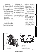
at the bottom of the boiler (Fig. 2-2).
N.B.:
close the valve after the operation.
If pressure values reach around 3 bar the safety
valve may be activated.
In this case contact a professional technician
for assistance.
In the event of frequent pressure drops, contact
qualified staff for assistance to eliminate the
possible system leakage.
2.9 SYSTEM DRAINING.
To drain the boiler, use the special draining
valve (Fig. 2-2).
Before draining, ensure that the filling valve is
closed.
2.10 ANTI-FREEZE PROTECTION.
The boiler is equipped with an antifreeze
function, as per standard, that activates pump
and burner operation when the temperature
of the water inside the boiler falls below 4°C
and stops when it reaches 42°C. The antifreeze
function is only guaranteed if the boiler is
fully operative, is not in "block" status and is
electrically powered with the main selector on
Summer or Winter. To avoid keeping the system
switched on in case of a prolonged absence, the
system must be drained completely or antifreeze
substances must be added to the heating system
water. In both cases the boiler domestic hot
water circuit must be drained. In systems that
are drained frequently, filling must be carried out
with suitably treated water to eliminate hardness
that can cause lime-scale.
Fig. 2-2
2.11 CASE CLEANING.
Use damp cloths and neutral detergent to clean
the boiler casing. Never use abrasive or powder
detergents.
2.12 DECOMMISSIONING.
In the event of permanent shutdown of the boiler,
contact professional staff for the procedures and
ensure that the electrical, water and gas supply
lines are shut off and disconnected.
Bottom view.
Key:
1 - System draining valve
2 - System filling valve
3 - Cold water inlet valve
4 - Gas cock
N.B.: connection group (optional)
Summary of Contents for 3.018921
Page 1: ...NIKE MINI 28 KW SPECIAL Instruction and warning booklet 1 040845ENG...
Page 21: ......
Page 22: ......
Page 23: ......


