40
INS
TALLER
US
ER
MAINTEN
AN
CE TECHNI
CI
AN
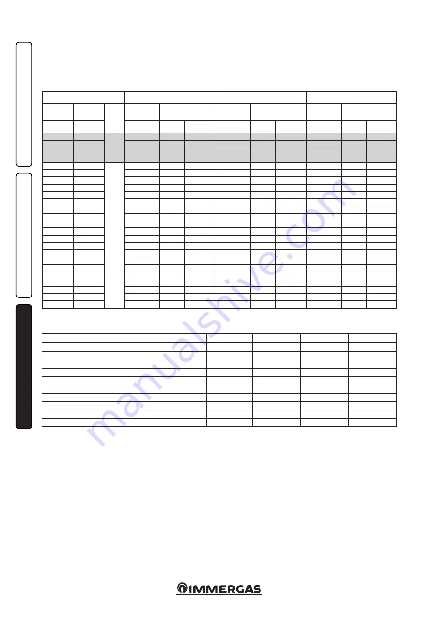
3.20 VARIABLE HEAT OUTPUT.
N.B.:
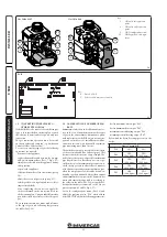
the pressures indicated in the table repre-
sent the differences of pressures at the ends of
the Venturi mixer and can be measured from the
pressure points in the upper part of the sealed
chamber (see pressure test 15 and 16 Fig. 1-27).
The adjustments must be made with a digital
differential pressure gauge with scale in tenths
of a mm or Pascal. The power data in the table
has been obtained with an intake-exhaust pipe
measuring 0.5 m in length. Gas flow rates refer
to the lower calorific value at a temperature of
15°C and at a pressure of 1013 mbar. The burner
pressure values refer to the use of gas at a tem-
perature of 15°C.
METHANE (G20)
BUTANE (G30)
PROPANE (G31)
THERMAL
POWER
THERMAL
POWER
BURNER GAS
FLOW RATE
PRESS. BURNER
NOZZLES
BURNER GAS
FLOW RATE
PRESS. BURNER
NOZZLES
BURNER GAS
FLOW RATE
PRESS. BURNER
NOZZLES
(kW)
(kcal/h)
(m
3
/h)
(mbar) (mm H
2
O)
(kg/h)
(mbar) (mm H
2
O)
(kg/h)
(mbar) (mm H
2
O)
2
5
.
7
22
1
0
2
D.H.W.
2.
79
5.
63
5
7
.
4
2.
08
5.
53
5
6
.
4
2.0
5
7.
13
7
2
.
7
25.0
21500
2.71
5.32
54.3
2.02
5.23
53.3
1.99
6.77
69.0
24.0
20640
2.60
4.91
50.1
1.94
4.82
49.2
1.91
6.28
64.0
23.6
20296
CEN.
HEAT.
+
D.H.W.
2.55
4.75
48.5
1.90
4.66
47.6
1.87
6.08
62.1
2
3
.
5
20210
2.
54
4.
72
4
8
.
1
1.
90
4.
63
4
7
.
2
1.
87
6
.
04
61
.
6
21.
0
18
060
2.
26
3
.
81
38
.
8
1.
69
3.
73
38.0
1.
66
4
.
94
5
0
.
4
20.0
17200
2.16
3.48
35.5
1.61
3.40
34.7
1.58
4.54
46.3
19.0
16340
2.05
3.17
32.3
1.53
3.10
31.6
1.50
4.15
42.4
18.0
15480
1.94
2.87
29.3
1.45
2.81
28.6
1.42
3.79
38.7
17.0
14620
1.84
2.59
26.5
1.37
2.53
25.8
1.35
3.45
35.1
16.0
13760
1.73
2.33
23.8
1.29
2.28
23.2
1.27
3.12
31.8
15.0
12900
1.63
2.09
21.3
1.21
2.03
20.7
1.19
2.81
28.6
14.0
12040
1.52
1.85
18.9
1.13
1.81
18.4
1.12
2.51
25.6
13.0
11180
1.42
1.64
16.7
1.06
1.59
16.3
1.04
2.23
22.8
12.0
10320
1.31
1.43
14.6
0.98
1.40
14.2
0.96
1.97
20.1
11.0
9460
1.21
1.24
12.7
0.90
1.21
12.3
0.89
1.72
17.5
10.0
8600
1.10
1.06
10.8
0.82
1.04
10.6
0.81
1.49
15.1
9.0
7740
1.00
0.90
9.2
0.74
0.88
9.0
0.73
1.26
12.9
8.0
6880
0.89
0.75
7.6
0.67
0.74
7.5
0.65
1.06
10.8
7.0
6020
0.78
0.61
6.2
0.59
0.60
6.2
0.58
0.87
8.8
6.0
5160
0.68
0.49
5.0
0.51
0.49
5.0
0.50
0.69
7.0
5.0
4300
0.57
0.38
3.9
0.42
0.38
3.9
0.42
0.52
5.3
4.0
3440
0.46
0.28
2.9
0.34
0.29
3.0
0.34
0.37
3.8
3.0
2580
0.35
0.20
2.0
0.26
0.22
2.2
0.25
0.24
2.4
3.21 COMBUSTION PARAMETERS.
G20
G30
G31
Supply pressure
mbar (mm H
2
O)
20 (204)
29 (296)
37 (377)
Gas nozzle diameter (Gas valve 8205)
mm
5.50
4.00
4.00
Gas nozzle diameter (Gas valve 848)
mm
5.40
4.00
4.00
Flue flow rate at nominal heat output
kg/h
42
3
7
43
Flue flow rate at min heat output
kg/h
6
5
6
CO
2
at Q. Nom./Min.
%
9.
4
0 / 8.
70
12.30 / 11.
1
0
10.40 /
9
.
7
0
CO with 0% O
2
at Nom./Min. Q. Nom./Min.
ppm
17
5
/
4
6
6
0 / 4
1
9
0 /
4
NO
X
at 0% of O
2
at Q. Nom./Min.
mg/kWh
5
5 / 1
4
107 / 19
20 / 3
Flue temperature at nominal output
°C
62
70
63
Flue temperature at minimum output
°C
54
60
54

