background image

5

INS

TALLER

US

ER

MAINTEN

AN

CE TECHNI

CI

AN

1

  DEVICE  

INSTALLATION

1.1  DESCRIPTION OF THE DEVICE.

The Immergas solar solutions systems are sup-

plied complete for its commissioning with exclu-

sion of fixing systems (e.g. plugs etc.).

The solar collectors are certified and are in com-

pliance with the standards  Solarkeymark. They 

can be mounted on all roof types or directly on 

the ground by means of an additional appropri-

ate structure.

The purpose of this manual is to give general 

indications on its installation and relative use of 

the complete system.

Installation must be carried out in compliance 

with current regulations and by qualified staff.

Installation must be carried out according to the 

standards, current legislation and in compliance 

with local technical regulations and the enabled 

companies.

In the event the pack is installed in damp places, 

one must provide an insulation system under-

neath it, to insulate it from the ground.

The place of installation of the appliance and 

relative Immergas accessories must have suitable 

features (technical and structural) such to allow 

(always in safety, efficiency and comfortable 

conditions):

-  installation (according to the provisions of the 

technical legislation and technical regulations);

-  maintenance operations (including scheduled, 

periodic, routine and special ones);

- removal (to outdoors in the place for loading 

and transporting the appliances and com-

ponents) as well as the eventual replacement 

of those with appliances and/or equivalent 

components.

Before installing the system, ensure that it is 

delivered in perfect condition; if in doubt, con-

tact the supplier immediately. Packing materials 

(staples, nails, plastic bags, polystyrene foam, 

etc.) constitute a hazard and must be kept out of 

the reach of children.

In case of failure to use the solar system or pro-

longed absences, cover the collectors to prevent 

overheating of the system. 

In the event of malfunctions, faults or incorrect 

operation, turn the system off immediately and 

cover it; it is also necessary to contact an author-

ised company (e.g. the Authorised Technical 

Assistance Centre, which has specifically trained 

staff and original spare parts). Do not attempt to 

modify or repair the appliance alone.Failure to 

comply with the above implies personal respon-

sibility and invalidates the warranty.
“Anti-legionella” heat treatment of the Immergas 

storage tank (activated by the specific function 

present on the predisposed thermoregulatory 

systems): during this stage, the temperature of 

the water inside the storage tank exceeds 60°C 

with a relative risk of burns. Keep this domestic 

water treatment under control (and inform 

the users) to prevent unforeseeable damage 

to people, animals, things. If required install a 

thermostatic valve on the domestic hot water 

outlet to prevent scalding.
• Installation regulations: 
-  The control of the entire framework by a statics 

expert, according to the Standards in force, is 

mostly necessary in areas with large snowfall or 

in areas exposed to strong winds. Therefore, all 

characteristics of the place of assembly must be 

taken into consideration (gusts of wind, vortex 

build-up, etc...) which can lead to an increase 

of loads on the structures.

- before starting the system, the solar collector 

must be covered to protect the absorber from 

over-heating and the operator from eventual 

burns. The system must only be filled when 

all hydraulic connections have been coupled 

correctly. It cannot be started until it is possible 

to eliminate the heat generated by the solar 

collector.

-  The collector can be positioned on the basis of 

the conditions of the roof (flat or sloping) or in 

a prepared free structure. The collector cannot 

be positioned with the glass part facing down. 

This causes malfunctioning and damage.

- Pay attention not to force or put excessive 

traction on the collector connection fittings in 

order to prevent damage tot he same and the 

internal parts of the collector.

- During movement, use protective gloves and 

do not transport the collector holding it by the 

connection fittings.

Attention:

-  it is in fact obligatory to use antifreeze supplied 

by the manufacturer;

- when realising the hydraulic circuit (pipes, 

fittings, etc.), only use suitable materials that 

resist high temperatures and are suitable for 

use with solar systems.

-  the use of a boiler involves the installation of a 

safety valve, an expansion vessel and a one-way 

valve for the appropriately sized domestic hot 

water circuit, 

these components are not always  

included in the package.

N.B.:

 if errors occur during installation, running 

and maintenance, due to the non compliance of 

technical laws in force, standards or instructions 

contained in this book (or however supplied by 

the manufacturer), the manufacturer is excluded 

from any contractual and extra-contractual 

liability for any damages and the warranty is 

invalidated.

Summary of Contents for 3.027832

Page 1: ...V2 HEATING SOLAR PANELS PACKS IE Instruction booklet and warning 1 041485ENG...

Page 2: ......

Page 3: ...ls within the dimensional limits established by the Law Installation and maintenance must be performed in compliance with the regulations in force according to the manufacturer s instructions and by a...

Page 4: ...Inox Sol 500 V2 12 1 9 Inox Sol 500 Lux V2 13 1 10 Solar collectors 14 1 11 Control devices unit 16 1 12 Circulation unit 17 1 13 Hydraulic connection CP4XL flat collectors 18 1 14 Hydraulic connectio...

Page 5: ...ti legionella heat treatment of the Immergas storage tank activated by the specific function present on the predisposed thermoregulatory systems during this stage the temperature of the water inside t...

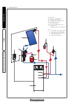
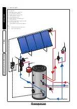
Page 6: ...it 2 N 1 individual solar circulation unit 3 N 1 18 l expansion vessel 4 N 1 6 bar safety valve 5 N 1 system probe and venting unit 6 N 1 mixing valve 7 frame and brackets for roof installation Key A...

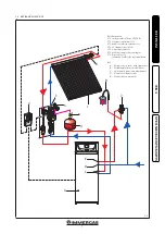
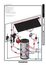
Page 7: ...l unit 2 N 1 double circulation solar unit 3 N 1 35 l expansion vessel 4 N 1 6 bar safety valve 5 N 1 probe unit and system venting 6 N 1 mixer valve 7 frame and brackets for roof installation Key A H...

Page 8: ...1 electronic control unit 2 N 1 single circulation solar unit 3 N 1 18 l expansion vessel 4 N 1 6 bar safety valve 5 N 1 probe unit and system venting 6 N 1 mixer valve 7 N 1 200 litre storage tank i...

Page 9: ...tor CSV14 1 N 1 electronic control unit 2 N 1 double circulation solar unit 3 N 1 35 l expansion vessel 4 N 1 6 bar safety valve 5 N 1 probe unit and system venting 6 N 1 mixer valve 7 N 1 200 litre s...

Page 10: ...N 1 electronic control unit 2 N 1 single circulation solar unit 3 N 1 18 l expansion vessel 4 N 1 6 bar safety valve 5 N 1 probe unit and system venting 6 N 1 mixer valve 7 N 1 300 litre storage tank...

Page 11: ...ctors CSV14 1 N 1 electronic control unit 2 N 1 double circulation solar unit 3 N 1 35 l expansion vessel 4 N 1 6 bar safety valve 5 N 1 probe unit and system venting 6 N 1 mixer valve 7 N 1 300 litre...

Page 12: ...electronic control unit 2 N 1 single circulation solar unit 3 N 1 35 l expansion vessel 4 N 1 6 bar safety valve 5 N 1 probe unit and system venting 6 N 1 mixer valve 7 N 1 500 litre storage tank in s...

Page 13: ...CSV14 1 N 1 electronic control unit 2 N 1 double circulation solar unit 3 N 1 80 l expansion vessel 4 N 1 6 bar safety valve 5 N 1 probe unit and system venting 6 N 1 mixer valve 7 N 1 500 litre stora...

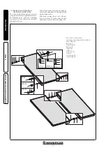
Page 14: ...the solar collector must be covered to protect the ab sorber from overheating and the operator from scalding The system must only be filled when the hydraulic system of the collector has been assembl...

Page 15: ...ef Opening surface W m2 K2 0 0161 K angle incidence 50 0 95 Heating capacity ceff 5 72 Maximum working pressure bar 10 Average flow l min 1 25 TECHNICAL FEATURES CSV Name Vacuum collector Dimensions m...

Page 16: ...installation ensure that the connection cable to the electric network and the probe cables remain separated The control unit is equipped with 3 relay to which to connect users such as pumps valves etc...

Page 17: ...for flow rate reading 15 Non return valve thermometer and cock 16 Degasser 17 Solar collector inlet 18 Boiler towards output 1 12 CIRCULATION UNIT The pump unit allows to connect the storage tank to...

Page 18: ...six collectors in series using the connection kits additional collectors N B when mounting the fittings including the air vent valve apply teflon or other material with similar characteristics N B bef...

Page 19: ...s supplied by Immergas The following can be connected to maximum six collectors in series using the connection kits additional collectors N B when mounting the fittings including the air vent valve ap...

Page 20: ...front and rear halves b drill two holes 8 on the wall in correspond ence with the holes on the supporting plate c fix the supporting plate to the wall by placing the rear half of the insulation casing...

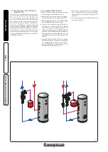
Page 21: ...he liquid contained in the solar circuit 1 20 FILLING SYSTEM The system can only be filled when the system is completely assembled any working residues have been eliminated that cause obstructions and...

Page 22: ...tive operations ensuring among other things that water supply is disconnected and the solar collector is covered At the end of its service life the appliance must not be disposed of like normal househ...

Page 23: ...ing checks and maintenance should be performed at least once a year Visually check for water leaks or oxidation from on connections Check visually that the safety and control devices have not been tam...

Page 24: ...mmergas com Immergas S p A 42041 Brescello RE Italy Tel 0522 689011 Fax 0522 680617 Certified company ISO 9001 This instruction booklet is made of ecological paper Cod 1 041485ENG rev ST 003408 000 11...

Reviews: