


17
4
2
4
3
1
5
6
6
6
6
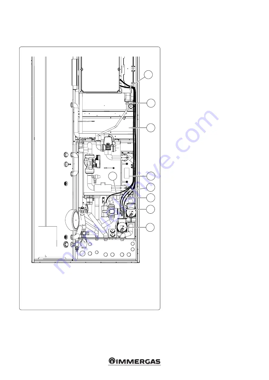
Key:
1 - Second mixed zone circulator connection
2 - Flow probe connection
3 - Safety thermostat connection
4 - 3-way valve connection
5 - Second mixed zone circulator
6 - Cable holders
Once the kit is assembled, proceed with the
wiring according to the wiring diagram in the
instruction booklet
.
- Connect the cables in the electrical panel of
the Indoor Unit as shown in Fig. 5..
- Lower the wiring coming out of the electri-
cal panel until it can be secured through the
clamps (6).
- Connect the connector of the delivery probe
(2) and of the safety thermostat (3).
- Connect the circulator (5) to the connector (1).
- Connect the 3-way mixing valve connector (4).
N.B.: wind the uncovered fittings with the
insulation present in the kit.
WIRING DIAGRAM FOR INDOOR UNIT WITH
OPTIONAL SECOND ZONE KIT IN SOLAR OR DOMUS
CONTAINER.


