background image

22

8

0

200

400

600

800

1000

1200

1400

1600

1800

2000

2200

2400

2600

0

20

40

60

80

2800

3000

10

30

50

70

0

10

0

20

40

60

80

10

30

50

70

10

A

X1

Y1

Y2

MIN

MIN

MAX

MAX

B

9

0

200

400

600

800

1000

1200

1400

1600

1800

2000

2200

2400

2600

0

20

40

60

80

2800

3000

10

30

50

70

0

10

0

20

40

60

80

10

30

50

70

10

A

X1

Y1

Y2

MIN

MIN

MAX

MAX

B

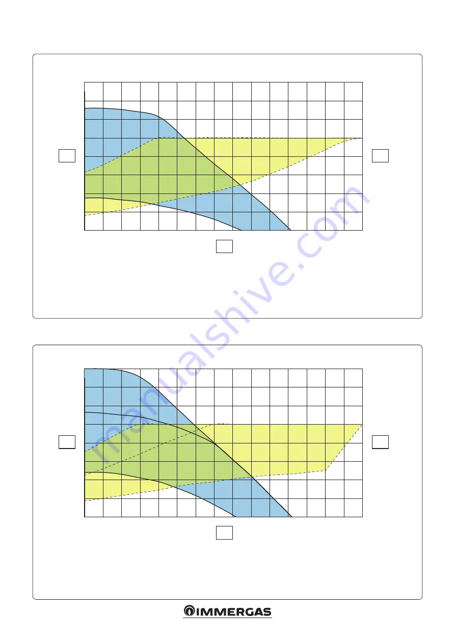
Total head available to the system of zone 1 direct constant head.

Total head available to the system of zone 2 mixed fixed speed - mixing valve open.

Key:

  A =  Total head available to the system

  B =  Power absorbed by the system pump (dotted area)

Key:

  A =  Total head available to the system

  B =  Power absorbed by the system pump (dotted area)

Ci

rcu

la

to

r p

um

p a

bs

or

be

d p

ow

er

 (W

)

Flow rate (l/h)

H

ea

d (kP

a)

Flow rate (l/h)

H

ea

d (kP

a)

Ci

rcu

la

to

r p

um

p a

bs

or

be

d p

ow

er

 (W

)

Summary of Contents for 3.031483

Page 1: ...COD 3 031483 KIT AGGIUNTIVO 2a ZONA MISCELATA PER TRIO PACK ADDITIONAL KIT 2nd MIXED ZONE FOR TRIO PACK IT Foglio istruzioni e avvertenze Instruction and warning book IE...

Page 2: ...rientamento della valvola miscela trice come rappresentato nel dettaglio in Fig 3 collegare il tubo di mandata seconda zona 25 alla valvola miscelatrice 16 interponendo la guarnizione di tenuta 11 e a...

Page 3: ...3 2 4 3 1 1 2 Legenda 1 Raccordo di scarico 2 Accumulo 3 Tappo 4 Tappo TRIO PACK IN SOLAR O DOMUS CONTAINER TRIO PACK CON KIT 2A ZONA MISCELATA IN SOLAR O DOMUS CONTAINER...

Page 4: ...x2 12 1 Tubo ritorno impianto seconda zona 13 1 Coibentazione con velcro 14 1 Coperchio motore tre vie 15 1 Motore valvola miscelatrice 16 1 Valvola miscelatrice 17 1 Coibentazione valvola miscelatric...

Page 5: ...e il connettore della sonda di mandata 2 e del termostato sicurezza 3 Collegare il circolatore 5 al connettore 1 Collegare il connettore della valvola miscela trice a 3 vie 4 N B avvolgere i raccordi...

Page 6: ...a bassa temperatura M10 2 Circolatore zona 2 M31 2 Valvola miscelatrice zona 2 1 Chiuso 2 Comune 3 Aperto 4 Pannello principale Legenda codici colori BK Nero BL Blu BR Marrone G Y Verde Giallo GY Grig...

Page 7: ...la possibilit di avere fastidiosi rumori di flusso d acqua nelle condutture nelle valvole e nei radiatori Condizioni ottimali di benessere termico e di benessere acu stico Prevalenza costante P C Il...

Page 8: ...lgimento Avvolgimentodifettoso Lampeggiacon lucerossa Sotto sovratensione Tensionedialimentazionelatoalimentazi onetroppobassa alta Controllarelatensionedireteele condizionid impiego richiedereil Cent...

Page 9: ...70 10 A X1 Y1 Y2 MIN MIN MAX M AX B Prevalenza disponibile all impianto zona 1 diretta velocit fissa Prevalenza disponibile all impianto zona 1 diretta prevalenza proporzionale Legenda A Prevalenza di...

Page 10: ...Y1 Y2 MIN MIN MAX MAX B Prevalenza disponibile all impianto zona 1 diretta prevalenza costante Prevalenza disponibile all impianto zona 2 miscelata velocit fissa valvola miscelatrice aperta Legenda A...

Page 11: ...AX B Prevalenza disponibile all impianto zona 2 miscelata prevalenza proporzionale valvola miscelatrice aperta Prevalenza disponibile all impianto zona 2 miscelata prevalenza costante valvola miscelat...

Page 12: ...alvola unidirezionale 16 Filtro ispezionabile optional 17 Filtro ispezionabile 18 Termostato antigelo 19 Valvola di sicurezza 8 bar 20 Rubinetto di svuotamento bollitore 21 Rubinetto intercettazione v...

Page 13: ...14 Valvola unidirezionale 15 Filtro ispezionabile optional 16 Filtro ispezionabile 17 Termostato antigelo 18 Valvola di sicurezza 8 bar 19 Rubinetto di svuotamento bollitore 20 Rubinetto intercettazi...

Page 14: ...ented in detail in Fig 3 Connectthesecondzonedeliverypipe 25 tothemixingvalve interposing the sealing gasket 11 and to the accumulation 2 interposing the sealing gasket 6 pre mount the safety thermost...

Page 15: ...15 2 2 4 3 1 1 TRIO PACK IN SOLAR OR DOMUS CONTAINER TRIO PACK WITH 2nd MIXED ZONE KIT IN SOLAR OR DOMUS CONTAINER Key 1 Drain fitting 2 Accumulation 3 Cap 4 Cap...

Page 16: ...y thermostat 10 2 Fixing screws 11 3 Gasket 30x22x2 12 1 Second zone system return pipe 13 1 Velcro insulation 14 1 Three way motor cover 15 1 Mixing valve motor 16 1 Mixing valve 17 1 Mixing valve in...

Page 17: ...t Connect the cables in the electrical panel of the Indoor Unit as shown in Fig 5 Lower the wiring coming out of the electri cal panel until it can be secured through the clamps 6 Connect the connecto...

Page 18: ...E7 2 Low Temperature safety thermostat M10 2 Zone 2 pump M31 2 Zone 2 mixing valve 1 Close 2 Common 3 Open 4 Main panel Colour code key BK Black BL Blue BR Brown G Y Green Yellow GY Grey OR Orange W...

Page 19: ...s valves and radiators is eliminated by reducing the head Optimal conditions for thermal comfort and acoustic well being Constant head P C The circulator pump maintains the pressure level head constan...

Page 20: ...ng Itflasheswith redlight Under Overvoltage Feedsidepowersupplyvoltagetoolow high Checkthemainsvoltageandoperating conditions asktheAuthorised TechnicalAssistanceCentre Excessive module tem perature I...

Page 21: ...40 60 80 10 30 50 70 10 A X1 Y1 Y2 MIN MIN MAX M AX B Total head available to the system of zone 1 direct fixed speed Total head available to the system of zone 1 direct proportional head Key A Total...

Page 22: ...80 10 30 50 70 10 A X1 Y1 Y2 MIN MIN MAX MAX B Total head available to the system of zone 1 direct constant head Total head available to the system of zone 2 mixed fixed speed mixing valve open Key A...

Page 23: ...0 50 70 10 A X1 Y1 Y2 MIN MIN MAX MAX B Total head available to the system of zone 2 mixed fixed speed mixing valve open Total head available to the system of zone 2 mixed constant head mixing valve o...

Page 24: ...14 Direct zone circulator 15 One way valve 16 Inspectionable filter optional 17 Inspectionable filter 18 Antifreeze thermostat 19 8 bar safety valve 20 Tank unit draining valve 21 DHW vessel shut off...

Page 25: ...r optional 13 Direct zone circulator 14 One way valve 15 Inspectionable filter optional 16 Inspectionable filter 17 Antifreeze thermostat 18 8 bar safety valve 19 Tank unit draining valve 20 DHW vesse...

Page 26: ...26...

Page 27: ...27...

Page 28: ...ducts that are correctly installed and used with respect to the Standards in force N B correct periodic maintenance is highly recommended Immergas TOOLBOX L App studiata da Immergas per i professionis...

Reviews: