68
INS
TALLER
US
ER
MAINTEN
AN
CE TECHNI
CI
AN
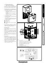
Setting menu.
This menu features all the adjustable parameters
for your system. The various parameters are not
available on all systems.
To access the Setting menu, press the (-
◀
) and
(
▶
+) keys at the same time. When you access the
Installation menu (the first parameter “
TkM1
”
is displayed), it is possible to select another
parameter by pressing the (
OK
) navigation key.
Once the desired parameter is displayed, it is
possible to change the value using the (
▶
+) or
(-
◀
) keys.
- Maximum temperature in tank 1.
“
TkM1
” parameter (default value “65°C”).
- Maximum value of the desired temperature
of the water in tank 1 during normal opera-
tion. (Adjustable b15 and 95°C with
default value 65°C).
- Maximum delta temperature for tank 1
“
dtM1
” parameter (default value “15°C”).
- Difference between temperature
T1
of the
manifold and temperature
T2
of tank 1 to
activate main pump 1. (Adjustable between
3 and 40°C with recommended temperature
7°C).
- Minimum delta temperature for tank 1.
“
dtm1
” parameter (default value “7°C”).
- Difference between temperature
T1
of the
manifold and temperature
T2
of tank 1 to
stop main pump 1. (Adjustable between 2
and (tank.1 dTMax -2°C) with recommended
temperature 3°C).
- Minimum manifold temperature.
“
mtCo
” parameter (default value “25°C”).
- This setting is used to define a minimum
temperature on the manifold, to authorise
the solar charge. (Adjustable between 0°C
and 99°C with default value 25°C).
Cooling.
“
Cool
” parameter (default value “On”).
This option is used to protect the manifold liquid
and operates as described below. Activate solar
pump
P1
or
P2
if the temperature of the set of
manifolds
T1
or
T4
exceeds the “
Max temp
”
value, even if the maximum temperature set in
the tank is exceeded. Circulation stops when the
temperature has dropped by 10°C. (The pumps
stop if the temperature of the water in the tank
reaches 90°C).
“
Rcoo
” parameter (default value “On”).
When the temperature of the water in the tank
exceeds the level set in “Maxtemp tank1” and
the temperature of the manifold has gone down
by 10°C, the pump starts-up to cool down the
tank via the manifolds. The pump will switch off
when the temperature of the water drops below
the level set in “
tkM1
” or when the difference
between the temperature of the set of manifolds
and of the tank is below 2°C.
Antifreeze protection.
“
FrEZ
” parameter (default value “off”)
This option maintains the temperature of solar
panel
T1
or
T4
above the level set for freezing
with the “
Frzt
” parameter, activating pump
P1
or
P2
.
This option can be used to reduce the build-up
of snow on the panel and to increase the effi-
ciency during the day or prevent damage to the
solar liquid.
N.B.:
it is preferable not to use this function
in very cold places to prevent using too much
energy accumulated in the tank.
- To activate the function, press (
▶
+) and select
“on“.
- Now you can adjust the Freezing setting.
“
FrZt
” parameter (default value “10°C” (Adjusta-
ble between -20°C and + 7°C with recommended
value 3°C).
Display.
“
DiSP
” parameter (default value “OFF”).
Back-lighting function.
- To enable or disable the back-lighting function
press (
▶
+) or (-
◀
).
- If it is “
Off
” the back-lighting will switch off
automatically 3 minutes after having pressed
the key.
- If it is “
On
” the back-lighting will always be
active.
Factory setting.
“
Fact
” parameter.
- If you want to reload all the parameters with
factory settings, press and hold the (
▶
+) key
for a few seconds.
N.B.:
For safety and error prevention purposes,
the system selected will not be reset.
System selection.
“
SySt
” parameter (Default value “
1
” not editable).
System 1.
Base system with 1 tank, 1 pump, 1 series of man-
ifolds and 2 sensors. It can be enriched by extra
functions with 1 or 2 T3 (NTC) or T4 (PT1000)
sensors (Thermostat, Cooling, Anti-stagnation
or Diff control function).
P1
T1
T2
Tank 1 can be loaded if the temperature differ-
ence “
dt
” between manifold (T1) and tank 1
(T2) is sufficient.
Manifold selection.
“
TubE
” parameter (Default value “off”).
After selecting the “
TubE
” parameter, press the
navigation key to the right (
▶
+) to select the type
of manifold installed.
- Now select “on” if your system uses a manifold
with vacuum pipes. (This function can also
be used with a flat manifold if the sensor is
mounted on the outside of the manifold). This
function works as follows. Every 30 minutes the
pump is activated for 40 seconds to measure
the correct value on the manifold and prevent
a short charging cycle.
- Select “off ” if the system works with a flat
manifold in normal operating conditions.
Maximum manifold temperature.
“
ColM
” parameter (default value “120”).
- Set the level to start the overheating protection
for the manifold. (Adjustable between 110 and
150°C, with default value 120°C)
Overheating protection.
“
OvrH
” parameter (default value “on”).
This function will stop the circulation of all the
manifolds (P1 and P2) when the temperature
of the manifold increases above “
ColM
” plus
a compensation value (default value +10°C,
modifiable). This function is used to protect the
system elements (pipes, fittings, ring-shaped
rubber gaskets).
- To activate the function, press (
▶
+) selecting
“on“.
- Now you can adjust the compensation level.
“
Ovrt
” parameter (default value “20°C”).
This compensation is normally used to prevent
an excessively fast reaction of the overheating
protection function (particularly useful with
vacuum pipe manifolds).
(Adjustable b10°C and +30°C with
default value +10°C).
N.B.:
For safety reasons, the overheating protec-
tion function must always be set at (“on”).
34
Summary of Contents for BASIC MAGIS PRO
Page 18: ...19 20 18 INSTALLATORE UTENTE MANUTENTORE Dett 1 Dett 2 ...
Page 21: ...24 25 Dett 2 Dett 3 21 INSTALLATORE UTENTE MANUTENTORE Dett 1 ...
Page 23: ...28 6 7 B B B 8 MP RP UCS EFS RP MP 9 23 INSTALLATORE UTENTE MANUTENTORE ...
Page 44: ...IE ...
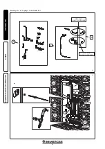
Page 60: ...60 INSTALLER USER MAINTENANCE TECHNICIAN 19 20 Det 2 Det 1 ...
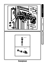
Page 63: ...63 INSTALLER USER MAINTENANCE TECHNICIAN 24 25 Dett 2 Dett 3 Det 3 Det 2 Det 1 ...
Page 65: ...65 INSTALLER USER MAINTENANCE TECHNICIAN 28 6 7 B B B 8 MP RP UCS EFS RP MP 9 ...
Page 86: ...86 ...
Page 87: ...87 ...

