background image

10

13

12

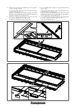
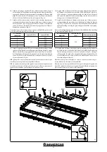
11)  Fissare i carter laterali utilizzando le 6 squadrette fissaggio carter (3 per 

lato) e fissare queste ultime in corrispondenza dei traversini del tetto con 

le viti 4x35 (Fig. 12).

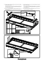
12)  Predisporre una cordonatura di silicone lungo il perimetro sul lato interno 

delle 4 squadrette ispezione (Fig. 13).


Montare le 4 squadrette chiusura ispezione con le relative viti AF 4,2x13 

in tutte e 4 le aperture ispezione poste sui carter laterali (Fig. 13).

11)  Fix the side guards with the 6 guard fixing brackets (3 per side) to the roof 

crosspieces with the 4x35 screws (Fig. 12).

12) Apply a bead of silicone along the perimeter on the inside of the 4 inspection 

brackets (Fig. 13).


Mount the 4 inspection closure brackets using the 4.2x13 self-tapping 

screws in all 4 of the inspection openings on the side guards (Fig. 13).

Summary of Contents for CP4 XL/M

Page 1: ... COD 3 027736 KIT ESTENSIONE MONTAGGIO ORIZZONTALE COD 3 027769 CP4 XL M COD 3 027849 KIT ESTENSIONE IE Instruction booklet and warning RECESSED KIT WITH OUTFLOW FRAME FOR FLAT PLATE THERMAL SOLAR MANIFOLD VERTICAL INSTALLATION CODE 3 027735 CP4 XL CODE 3 027768 CP4 M CODE 3 027736 EXTENSION KIT HORIZONTAL INSTALLATION CODE 3 027769 CP4 XL M CODE 3 027849 EXTENSION KIT ...

Page 2: ...8 Installazione collettori multipli lato lungo 18 VERTICAL INSTALLATION 3 Description 3 Composition of the recessed Kit 3 Composition of EXTENSION Kit for recessed kit 3 Overall dimensions 4 General recommendations 5 Installazione collettore singolo lato lungo 5 LONG side multiple manifold installation 5 HORIZONTAL INSTALLATION 16 Composition of the recessed Kit 16 Composition of EXTENSION Kit for...

Page 3: ...ER KIT INCASSO Descrizione Qtà Rotolo 1 Base di sostegno 1 Vite per legno 5x70 2 Vite 4x35 12 Viti AF 4 2x13 4 Scolo 1 Squadretta posizionamento collettore 2 Staffa fissaggio collettore 3 Carter mediano 1 Carter superiore 1 Chiusura carter mediano 2 INSTALLAZIONE VERTICALE IT General recommendations This kit must be installed in compliance with the regulations in force according to the instruction...

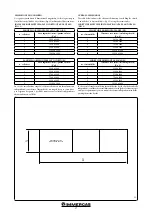
Page 4: ... un singolo kit per comodità e per esigenze di spazio è possibile montare vari collettori indipendenti affiancandone uno all altro OVERALL DIMENSIONS The table below indicates the clearance dimensions excluding the sheath to install the 1 to 6 manifold kit Fig 1 using the extension kit LONG SIDE MULTIPLE INSTALLATION CP4 XL AND CP4 M FIG 1 no of manifolds Clearance area mm excluding sheath X x Y 1...

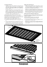
Page 5: ...a guaina adesiva Fig 3 per la lunghezza necessaria fare riferimento alla quota X indicata nella tabella riportata in precedenza N B le guaine adesive Fig 3 vanno ripiegate di circa 50 mm sul lato lungo superiore senza schiacciarle per impedire riflussi d acqua piovana GENERAL RECOMMENDATIONS Caution to prevent any infiltration of water it is essential to seal the roof attachment holes by means of ...

Page 6: ...redisposti seguendo le quoteriportatenellaFig 5 fissandolesquadrettevengonoautomaticamente fissati anche gli scoli precedentemente posizionati in Fig 4 3 Position the bottom drains Fig 4 on the roof crosspiece A so that they overlap the sheath as shown in Fig 5 The drains will overlap each other to completely cover the X measurement shown in the previous table Fig 1 Refer to the overlapping measur...

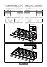
Page 7: ...nza dei fori già predisposti ai traversini del tetto 6 Inserire ogive e raccordi di collegamento sul 1 collettore Fig 7 5 Position the 1st manifold Fig 6 at 250 mm from the internal edge of the left drain make sure it is properly resting on the manifold positioning brackets and fix it with the 6 brackets to the roof crosspieces by screwing the 4x35 screws provided into the prepared holes 6 Insert ...

Page 8: ... collettori e fare pressione dove sono state applicate le cordonature di silicone per farlo aderire bene ai collettori Fig 9 7 Position the 2nd manifold and connect it to the 1st one keeping a distance of 56 mm between them Fig 8 make sure the 2nd collector is properly resting on the manifold positioning brackets and then fix it on the side without brackets using the other 3 brackets with the 4x35...

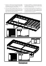
Page 9: ...n modo da avere già i relativi centraggi sul collettore e far aderire il silicone appena steso contro il lato del collettore Fig 11 9 Close the middle guard on both the top and bottom sides with the relative guard closure using the 4 2x13 self tapping screws Fig 10 Connect the manifolds 3 ways vents plugs etc 10 Apply a bead of silicone on the two left and right side guards along the entire side s...

Page 10: ...e Fig 13 Montare le 4 squadrette chiusura ispezione con le relative viti AF 4 2x13 in tutte e 4 le aperture ispezione poste sui carter laterali Fig 13 11 Fix the side guards with the 6 guard fixing brackets 3 per side to the roof crosspieces with the 4x35 screws Fig 12 12 Applyabeadofsiliconealongtheperimeterontheinsideofthe4inspection brackets Fig 13 Mount the 4 inspection closure brackets using ...

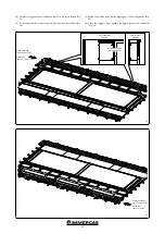
Page 11: ...OLAR MANIFOLD 13 Montare i tappetini adesivi sulla parte superiore dei carter laterali Fig 14 14 Posizionare le basi di sostegno contro la parte superiore dei collettori circa a metà di ciascun collettore Fig 15 13 Mount the sticky mats on the upper part of the side guards Fig 14 14 Place the support bases against the upper part of the manifolds at appro ximately halfway up each manifold Fig 15 ...

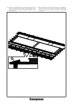
Page 12: ...oggiate contro i collettori e che le viti per legno 5x70 si fissino sul traversino del tetto sottostante Fig 16 15 Fix each base to the roof crosspieces with 2 5x70 wood screws C Fig 16 Make sure the support bases are properly resting against the manifolds and the 5x70 wood screws can be screwed to the crosspiece of the underlying roof Fig 16 ...

Page 13: ...o ai collettori assicurarsi che l incastro vada contro al collettore e non contro le squadrette di protezione poste agli angoli dei collettori stessi 16 Apply a bead of silicone on the left corner group along the edge indicated on the inner side at about the centre line of the folded bend place it on the wooden base slotting it sideways inside the bend of the side guard and against the manifold at...

Page 14: ...sini del tetto sottostante mediante le viti 4x35 N B assicurarsi di posizionare le squadrette come riportato nella Fig 19 19 Fix the top guards to the wooden bases with the 4x35 screws it is advisable to use at least 2 screws per guard and with a multiple kit it is advisable to place them on the overlapped part so one screw will fix 2 guards at a time Fig 18 Note It is recommended to apply a bead ...

Page 15: ...zionareletegoleinmododasormontareicarterdelkitelateralmente comprimendo le strisce isolanti Fig 21 21 Mount the adhesive insulating strips on the sides of the kit Fig 20 22 Reposition the roof tiles so as to overlap the kit guards and press sideways on the insulating strips Fig 21 ...

Page 16: ...retta posizionamento collettore 2 Staffa fissaggio collettore 3 Carter mediano 1 Scolo 2 Carter superiore 2 Chiusura carter mediano 2 INSTALLAZIONE ORIZZONTALE HORIZONTAL INSTALLATION DESCRIPTION The structure described below ensures horizontal installation of recessed solar manifolds in roofs This recessed system isolates the solar panel on the roof therefore no additional sealing adjustments are...

Page 17: ...i un singolo kit per comodità e per esigenze di spazio è possibile montare vari collettori indipendenti affiancandone uno all altro OVERALL DIMENSIONS The table below indicates the clearance dimensions excluding the sheath to install the 1 to 6 manifold kit Fig 22 using the extension kit SHORT SIDE MULTIPLE INSTALLATION CP4 XL AND CP4 M FIG 1 SHORT SIDE HORIZONTAL PANEL XL no of manifolds Clearanc...

Page 18: ...a guaina adesiva Fig 24 per la lunghezza necessaria fare riferimento alla quota X indicata nella tabella riportata in precedenza N B le guaine adesive Fig 24 vanno ripiegate di circa 50 mm sul lato lungo superiore senza schiacciarle per impedire riflussi d acqua piovana GENERAL RECOMMENDATIONS Caution to prevent any infiltration of water into the roofing it is essential to seal the roof attachment...

Page 19: ...a J Orizzontale XL 1800 Orizzontale M 1380 Fissando le squadrette vengono automaticamente fissati anche gli scoli precedentemente posizionati Fig 25 3 Position the bottom drains Fig 25 on the roof crosspiece A so that they overlap the sheath as shown in Fig 26 The drains will overlap each other to completely cover the X measurement shown in the previous table Fig 22 Refer to the overlapping measur...

Page 20: ...staffe tramite le altre 3 staffe con viti 4x35 Fig 28 8 Inserire ogive e raccordi di collegamento sul secondo collettore Fig 28 5 Position the 1st manifold Fig 27 at 250 mm from the internal edge of the left drain make sure it is properly resting on the manifold positioning brackets and fix it with the 6 brackets to the roof crosspieces by screwing the 4x35 screws into the prepared holes 6 Insert ...

Page 21: ... inferiore con i relativi carter chiusura utilizzando le viti AF 4 2x13 Fig 30 Procedere con il collegamento dei due collettori Fig 30 9 Note cut the middle guard at a length of 1175 mm and bend the ends as shown in Fig 29 Apply a bead of silicone along the two sides of the middle guard at ap proximately halfway up the bend Fig 29 Place the previously prepared middle guard with silicone between th...

Page 22: ...utilizzando le 6 squadrette fissaggio carter 3 per lato e fissare queste ultime in corrispondenza dei traversini del tetto con le viti 4x35 Fig 32 11 Apply a bead of silicone on the two left and right side guards along the entire side shown in Fig 31 Place the guards next to the manifolds they are shaped so as to be centred on the manifold and make the newly applied silicone stick against the side...

Page 23: ...PART ROOF FULL SIDE COLLETTORE SOLARE SOLAR MANIFOLD 13 Montare i tappetini adesivi sulla parte superiore dei carter laterali Fig 33 14 Posizionare le basi di sostegno contro la parte superiore dei collettori Fig 34 13 Mount the sticky mats on the upper part of the side guards Fig 33 14 Place the support bases against the upper part of the manifolds Fig 34 ...

Page 24: ...oggiate contro i collettori e che le viti per legno 5x70 si fissino sul traversino del tetto sottostante Fig 35 15 Fix each base to the roof crosspieces with 2 5x70 wood screws B Fig 35 Make sure the support bases are properly resting against the manifolds and the 5x70 wood screws can be screwed to the crosspiece of the underlying roof Fig 35 ...

Page 25: ...icontro ai collettori assicurarsi che l incastro vada contro al collettore e non contro le squadrette di protezione poste agli angoli dei collettori stessi 16 Apply a bead of silicone on the left corner group along the edge indicated on the inner side at about the centre line of the folded bend place it on the wooden base slotting it sideways inside the bend of the side guard and against the manif...

Page 26: ...sini del tetto sottostante mediante le viti 4x35 N B assicurarsi di posizionare le squadrette come riportato nella Fig 38 19 Fix the top guards to the wooden bases with the 4x35 screws it is advisable to use at least 2 screws per guard and with a multiple kit it is advisable to place them on the overlapped part so one screw will fix 2 guards at a time Fig 37 Note It is recommended to apply a bead ...

Page 27: ...zionareletegoleinmododasormontareicarterdelkitelateralmente comprimendo le strisce isolanti Fig 40 21 Mount the adhesive insulating strips on the sides of the kit Fig 39 22 Reposition the roof tiles so as to overlap the kit guards and press sideways on the insulating strips Fig 40 ...

Page 28: ...consulenza immergas com Torequestfurtherspecificdetails sector Professionals can also use the following e mail address consulenza immergas com Immergas S p A 42041 Brescello RE Italy Tel 0522 689011 Fax 0522 680617 Azienda certificata ISO 9001 ISO 9001 certified company Immergas TOOLBOX L App studiata da Immergas per i professionisti The App designed by Immergas for professionals Seguici su Immerg...

Reviews: