Technical documentation
Technical documentation
STEM@ ed 06/01
18
EOLO MAIOR @
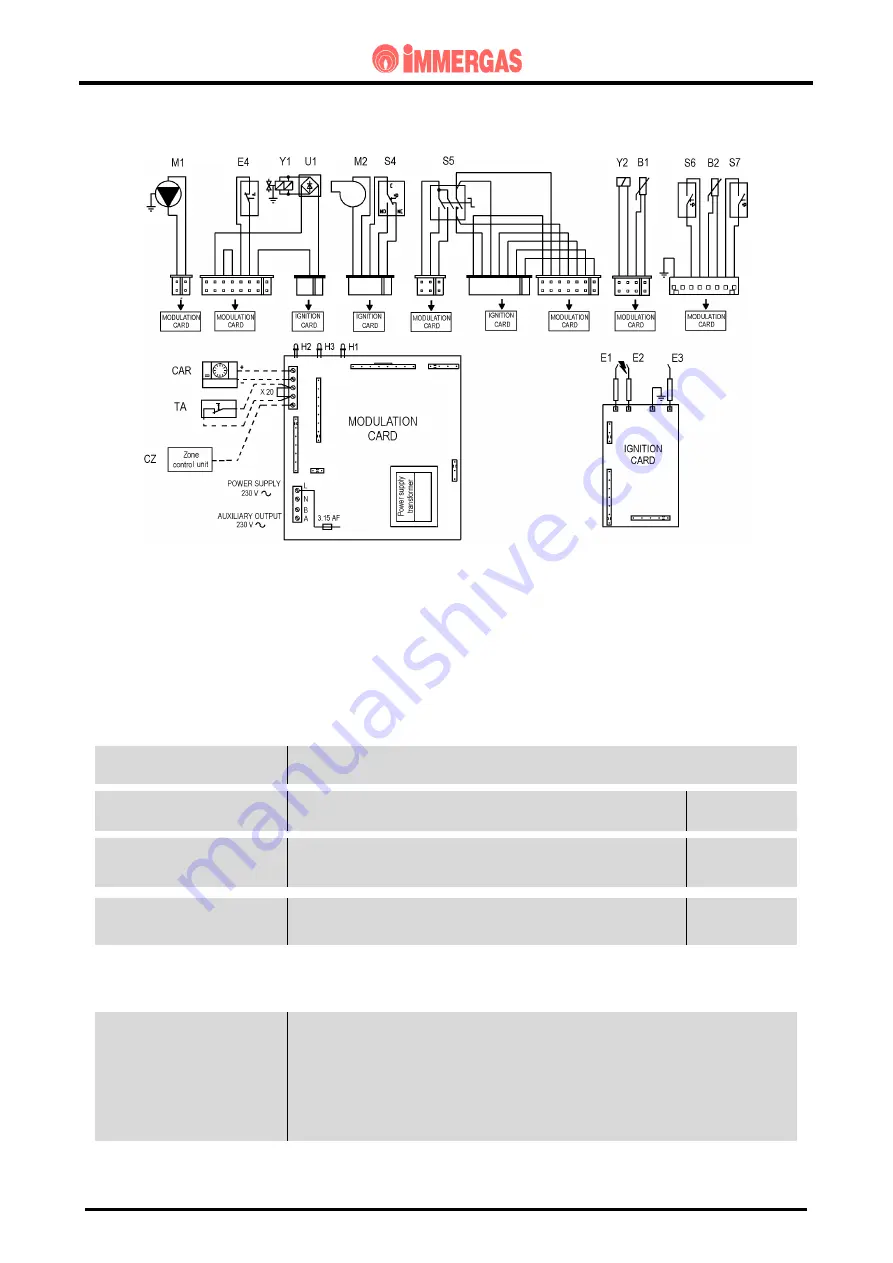
ELECTRICAL CIRCUIT
The electrical circuit of the EOLO MAIOR @ boilers is controlled by an electronic board that controls
all the boiler functions and to which the electrical devices on the machine are connected..
Some of the control and safety devices operate at mains voltage and others at low voltage.
230 V AC CIRCUIT
SAFETY DEVICES AND CONTROLS
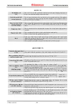
Detection electrode
(E3)
This detects ignition of the burner by whose flame it is invested.
It is connected to the detection circuit of the ignition unit
Fuse
This interrupts power to the circuit when power input is over 3.15 A.
It is fitted on the modulation board.
Fuse
3.15 A 250 V
Flue pressure switch (S4)
This controls the ignition unit and enables burner operation when fume
extraction occurs correctly.
If this is closed with the fan off, the ignition cycle will not start.
Two-position
switch
Overheat. safety device
(E4)
When the safety threshold is exceeded (115 ºC) this interrupts power
to the main coils of the gas valve (Y1).
It is located at the outlet of the primary exchanger.
Double-contact
clicson thermostat
LOADS
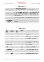
Ignition unit
(IGN. CARD)
This is controlled by the modulation board when burner ignition is required.
It controls the devices needed for ignition
(fan, main gas valve coils, ignition electrodes)
and flame detection
(detection electrode).
The power cables of the boiler envisage use of the B&P unit.
The use of a Brahma unit will require switchover of the two connection leads of the reset
button of the master switch S5.
NOTE. the instructions for performing this operation are shown on the EOLO Maior @
wiring diagrams in the “Wiring diagram” folder.


