20
STEkW ed 12/06
EOLO Maior kW
Technical Documentation
Technical Documentation
Only for 28 kW model.
(Up to serial number 2712127 for EOLO Maior 28 kW)
(Up to serial number 2711377 for EOLO Maior 28 kW X)
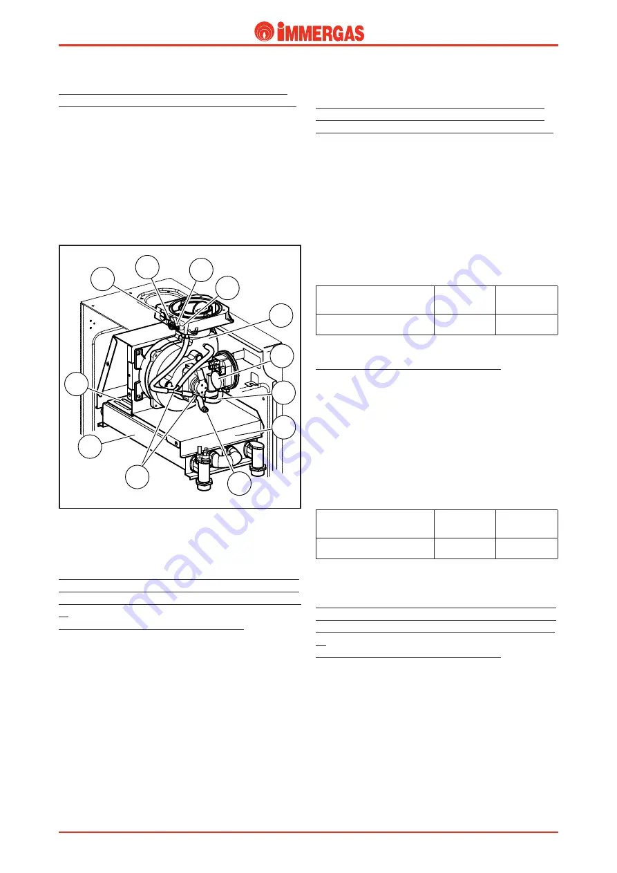
The negative pressure point (9) is connected to a “Y” shaped
pipe (11) which on one side
is connected to the pressure point
positioned at the outlet of the Venturi pipe inserted in the
fan’s exhaust terminal
and on the other side it is connected
to a second "Y" shaped pipe (11) whose one end is connected
to a calibrated nozzle (13) and the other end is connected
through a pipe (14)
to the negative pressure point of the
flue pressure switch (6).
The positive pressure point (10) is connected directly to the
inside of the sealed chamber.
Flue pressure switch signal pressure points (9-10).
(see figure on previous page).
(from the serial number 2738490 for EOLO Maior 24 kW)
(from the serial number 2712128 for EOLO Maior 28 kW)
(from the serial number 2711378 for EOLO Maior 28 kW
X)
(to start production for EOLO Maior 32 kW)
The top outer part of the sealed chamber features two pressure
points with screw closing by means of which it is possible to
measure the signal on the ends of the flue pressure switch
(6).
The negative pressure point (9) is connected to a “Y” shaped
pipe (11) which, in turn, is connected to the negative pressure
point of the flue pressure switch (6)
and to the pressure point
(1) positioned on the fan.
The positive pressure point (10) is connected directly to the
inside of the sealed chamber.
2
12
6
14
10
9
8
7
5
11
13
4
Flue pressure switch (6).
Only for 24 and 28 kW models.
(Up to serial number 2738489 for EOLO Maior 24 kW)
(Up to serial number 2712127 for EOLO Maior 28 kW)
(Up to serial number 2711377 for EOLO Maior 28 kW X)
It is located at the top inside the sealed chamber and detects, by
means of the relative points, the difference in pressure
between
the outlet of the Venturi pipe inserted in the fan exhaust
(negative signal)
and the inside of the sealed chamber
(positive signal)
.
The signal measured by the pressure switch is variable accord-
ing to the length of the air inlet/exhaust terminals and can be
measured by the relative pressure points located at the top of
the sealed chamber (9-10).
When it triggers it causes a switch to close (S6) that acts on the
integrated board enabling or preventing burner ignition.
Flue pressure switch
triggering pressures
ON
Pa (mm H
2
O)
ON
Pa (mm H
2
O)
EOLO 24-28 kW
150 (15.3)
130 (13.26)
Only for 32 kW model.
(to start production for EOLO Maior 32 kW)
It is located at the top inside the sealed chamber and detects, by
means of the relative points, the difference in pressure
between
the fan inside
(negative signal)
and the inside of the sealed
chamber
(positive signal)
.
The signal measured by the pressure swi
tch is variable accord-
ing to the length of the air inlet/exhaust terminals and can be
measured by the relative pressure points located at the top of
the sealed chamber (9-10).
When it triggers it causes a switch to close (S6) that acts on the
integrated board enabling or preventing burner ignition.
Flue pressure switch
triggering pressures
ON
Pa (mm H
2
O)
ON
Pa (mm H
2
O)
EOLO 32 kW
52 (5.3)
42 (4.3)
Flue pressure switch (6).
Only for 24 and 28 kW models.
(from the serial number 2738490 for EOLO Maior 24 kW)
(from the serial number 2712128 for EOLO Maior 28 kW)
(from the serial number 2711378 for EOLO Maior 28 kW
X)
(to start production for EOLO Maior 32 kW)
It is located at the top inside the sealed chamber and detects, by
means of the relative points, the difference in pressure
between
the fan inside
(negative signal)
and the inside of the sealed
chamber
(positive signal)
.
The signal measured by the pressure swi
tch is variable accord-
ing to the length of the air inlet/exhaust terminals and can be
measured by the relative pressure points located at the top of
the sealed chamber (9-10).
Summary of Contents for EOLO Maior kW
Page 2: ......


