9
1-5
1-6
1-7
45
31
58
INS
TALLER
US
ER
MAINTEN
AN
CE TECHNI
CI
AN
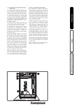
1.7 EXTERNAL TEMPERATURE PROBE
(OPTIONAL).
The boiler is designed for the application of the
Room Thermostat (Fig. 1-5) which is available
as an optional kit. Refer to the relative instruc-
tion sheet to position the external probe. The
probe can be connected directly to the boiler
electrical system and allows the max. system
flow temperature to be automatically decreased
when the external temperature increases, in
order to adjust the heat supplied to the system
according to the change in external tempera-
ture. The external probe always operates when
connected, regardless of the presence or type of
room chrono-thermostat used and can work in
combination with Immergas timer thermostats.
The electric connection of the external probe
must be made on clamps 38 and 39 on the boiler
P.C.B. (Fig. 3-2).
•
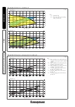
Direct Zone Check.
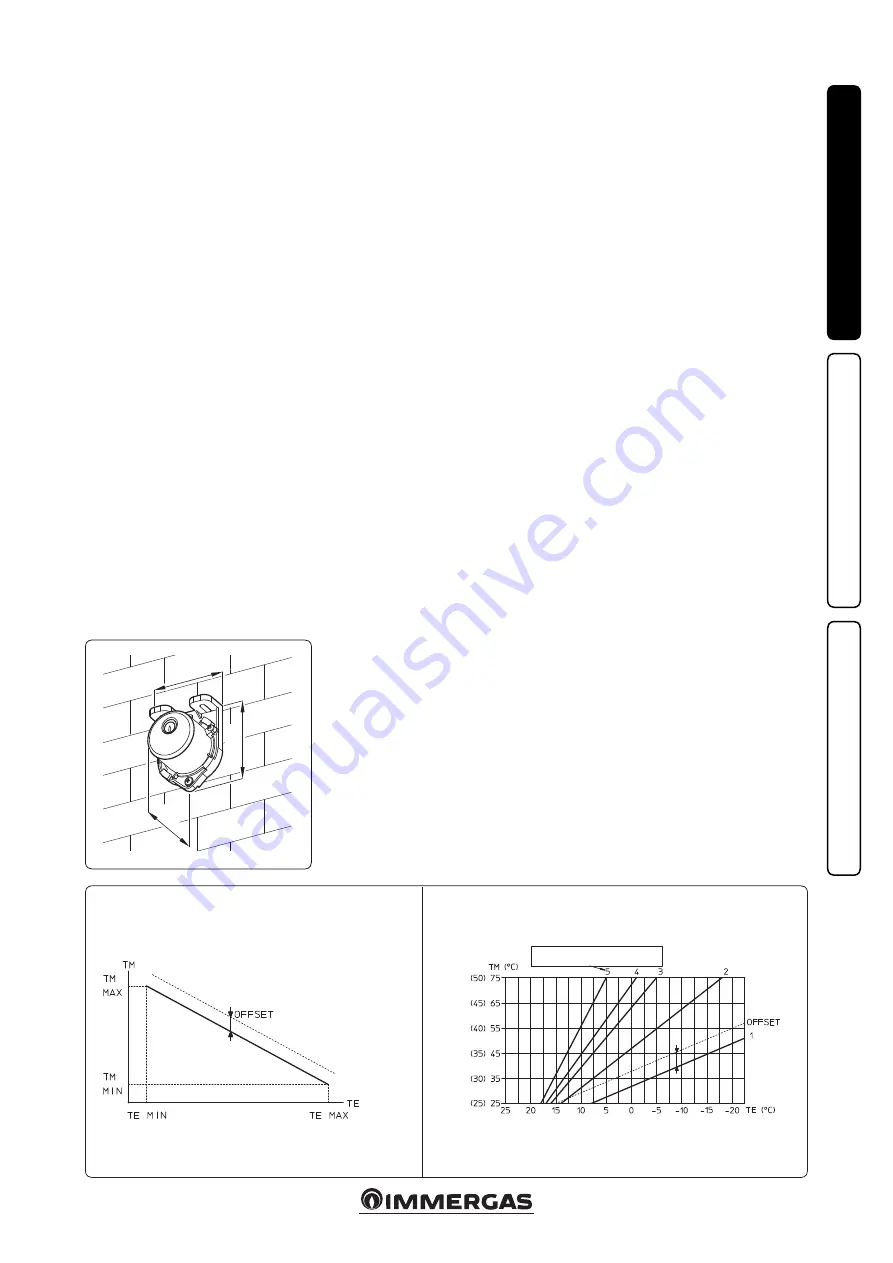
The correlation between
system flow temperature and external tem-
perature is determined by the parameters set in
menu “M5” under item “P66” according to the
curves represented in the diagram (Fig. 1-6).
•
Mixed Zone Check.
The correlation between
flow temperature to the system and external
temperature is determined by the position of
the trimmer (16 Fig. 3-5) on the zone board ac-
cording to the curve represented in the diagram
(Fig. 1-7).
TM - MAX/MIN = Direct temperature zone flow temperature
range selected.
TE = External temperature.
Direct Zone
Correction law of the flow temperature depending on the external tem-
perature and user adjustments of the central heating temperature.
Mixed Zone
Correction law of the flow temperature depending on the external temperature and
user adjustments of the central heating temperature.
TM = Mixed zone flow temperature
TE = External temperature.
POSITION OF THE TRIMMER
ZONE P.C.B.
In brackets, temperature value with 25°/50° range


