10
Inoxstor Pre-Plumbed Water Heater
Installation, Usage and Maintenance Instructions
4.3 THERMOSTAT WIRING
The Audax interface board has two connectors marked TH1 and TH2 which may be used to control the Audax using a ther-
mostat, chronostat, programmer or switch.
Each of these terminals has four pins, three of which provide L, N, E, and a switched input. Applying 230V to the switched
input will activate the zone valve and turn on the audax.
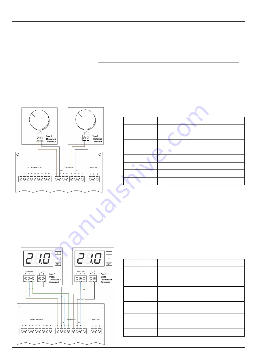
Here follows three example wiring diagrams.
Read and refer to the specific manufacturer's instructions for the type of
thermostat, chronostat, programmer, switch or other device used, prior to installation.
4.3.1 CONTROL USING 230V MECHANICAL THERMOSTATS
A mechanical thermostat may be used to switch 230V from the L pin of the TH1 or TH2 terminal to the SW pin.
4.3.2 CONTROL USING 230V DIGITAL OR DIGITAL PROGRAMMABLE THERMOSTATS
Where the external device requires 230V to operate, provide Live Neutral and Earth from either TH1 or TH2. The live should
be looped through the switched contact back to the SW pin on the TH1 or TH2 terminal.
Terminal
Pin
Use
TH1
L
To switch - Mechanical Thermostat for Zone 1
TH1
N
Not used
TH1
E
Not used
TH1
SW
From switch - Mechanical Thermostat for Zone 1
TH2
L
To switch - Mechanical Thermostat for Zone 2
TH2
N
Not used
TH2
E
Not used
TH2
SW
From switch - Mechanical Thermostat for Zone 2
Terminal
Pin
Use
TH1
L
Power supply to Zone 1 Thermostat.
Loop onto thermostat switch input.
TH1
N
Power supply to Zone 1 Thermostat.
TH1
E
Power supply to Zone 1 Thermostat.
TH1
SW
From switch - Mechanical Thermostat for Zone 1
TH2
L
Power supply to Zone 2 Thermostat.
Loop onto thermostat switch input.
TH2
N
Power supply to Zone 2 Thermostat.
TH2
E
Power supply to Zone 2 Thermostat.
TH2
SW
From switch - Mechanical Thermostat for Zone 2
Summary of Contents for INOXSTOR 200
Page 16: ...11 DECLARATION OF CONFORMITY ...
Page 17: ......


