5
Inoxstor Pre-Plumbed Water Heater
Installation, Usage and Maintenance Instructions
3. INSTALLATION
Carefully read and observe all instructions in the following sections. Failure to follow these instructions many
invalidate the warranty and / or lead to an unsafe situation.
3.1 RECOMMENDED HANDLING PROCEDURE
Keep the Inoxstor in its original packaging until time of installation to prevent damage. Do not store it outdoors or in any
damp location. Take care when lifting or moving the Inoxstor. Ensure that all local manual handling regulations are followed
to avoid the risk of injury.
Store the Inoxstor in a vertical orientation, resting on its base. Never lay the Inoxstor down horizontally. Take care not to dam-
age the manifold or any attached valves, devices , wiring or electronics when moving the Inoxstor.
3.2 LOCATION AND POSITIONING
The Inoxstor must be installed in a dry location, indoors. It is not suitable for outdoor use. The Inoxstor must be installed in a
vertical orientation.
Check the load bearing capacity of any floors or walls to ensure that they can support the weight of the water heater when
filled to capacity. Refer to section 2.3 for full weight of the water heater.
Enough space must be left at the top and sides of the unit for pipe connections and access to the safety controls and valves.
Refer to sections 2.1 and 2.2 to determine a suitable position for the heater. Allow sufficient clearance for access and service.
Ensure the location allows the Immersion to be removed if required.
Refer to sections 3.3 and 3.4 to determine which valves and accessories are required. Plumb the valves as shown in the rele-
vant diagrams. An isolating valve must be fitted on the cold water supply to the heater.
DO NOT
install the water heater where the unit may freeze.
DO NOT
mount the Inoxstor horizontally. It will not function correctly.
The Inoxstor must not be installed in a location where water leakage is likely to cause damage.
If it is necessary
to install the Inoxstor in such a location (e.g. an attic or higher floor of a building), a ‘tanked’, waterproof chamber
fitted with a drain should be created to ensure that any potential leaks from the product and associated fittings or
pipes are contained and drained away safely.
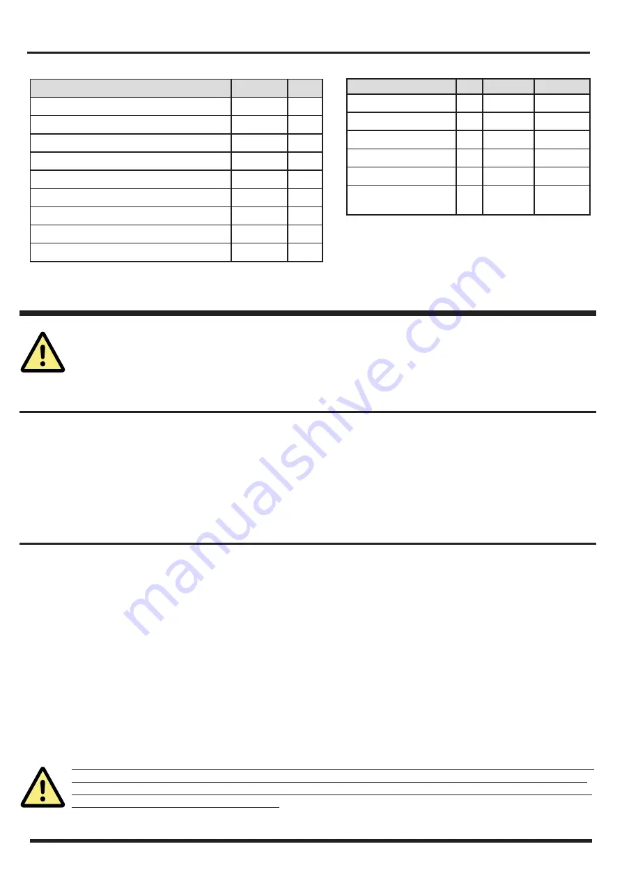
Hydraulic performance
Storage tank unit capacity
l
207
Domestic hot water side maximum pressure
bar
8
DHW side maximum temperature
°C
99
Maximum coil pressure
bar
6
Central heating side maximum temperature
°C
90
Empty storage tank unit weight
kg
65
Full storage tank unit weight
kg
279
Heat dispersion
kW h / 24 h 1.95
Psbsol
W/K
1.81
Upper coil Lower Coil
Exchange surface
m2
0.72
1.3
Coil capacity
l
4.1
7.5
Exchange power
kW
32
52
Primary fluid flowrate
l/h
1630
2950
Primary fluid T delta
°C
17
15
Useful reintegration
power
kW
26.3
34.3
2.3 TECHNICAL SPECIFICATIONS
Summary of Contents for INOXSTOR 200
Page 16: ...11 DECLARATION OF CONFORMITY ...
Page 17: ......


