Ventilatore Fumi
Exhaust Fan
24
Installation
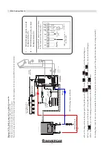
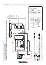
CONFIGURATION OF THE BOILER HYDRAULIC DIAGRAM
By a specialised technician
Before switching on the boiler, it is necessary to configure
the hydraulic diagram on which we want to work. The boiler
is set up to receive the potential-free contact of an external
thermostat (open/closed, the thermostat must not supply
voltage to the back.
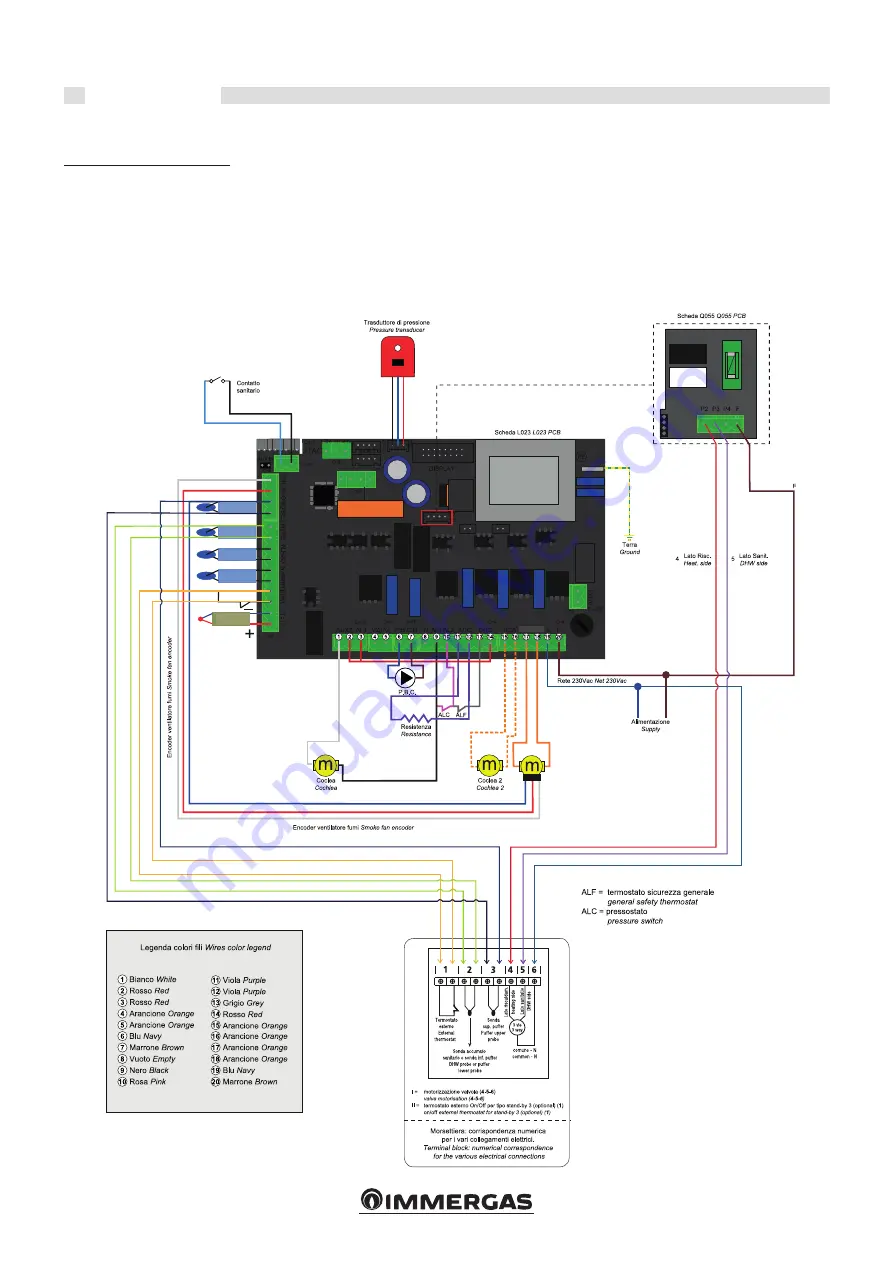
CONTROL UNIT WIRING DIAGRAM
DHW
contact
FLUE GAS
CONSOLES AND ADDITIONAL
ACCESSORIES CONVEYED WAVES
NTC S2 upper
puffer probe
NTC S1 lower
puffer probe
Boiler NTC
probe
NTC room
probe
ext.
thermostat
TCJ flue gas
probe
If the thermostat turns on the board and causes faults, the
warranty becomes void), two temperature probes and a
motorised valve. All these components can be connected via
the terminal block on the back of the boiler.


