background image

3-1

29  - IE

INS

TALLER

US

ER

MAINTEN

AN

CE TECHNI

CI

AN

3

  BOILER START-UP 

(INITIAL CHECK).

To commission the boiler:

- make sure that the declaration of conformity 

for installation is supplied with the appliance;

- make sure that the type of gas used corresponds 

to boiler settings;

- check  connection  to  a  230V-50Hz  power 

mains, correct L-N polarity and the earthing 

connection;

- make sure the central heating system is filled 

with water and that the manometer indicates 

a pressure of 1÷1.2 bar;

- check that the heat pump is connected and 

powered properly (see relative instructions 

manual);

- check that the common parameters between 

the heat pump and the boiler are configured 

properly;

- switch the boiler on and check correct ignition;
- check the ∆p gas values in domestic hot water 

and central heating modes;

- check the CO

2

 in the fumes at maximum and 

minimum flow rate;

- check activation of the safety device in the event 

of no gas, as well as the relative activation time;

- check  the  intervention  of  the  main  switch 

located upstream of the boiler and in the boiler;

- check that the intake and/or exhaust terminals 

are not blocked;

- ensure activation of all adjustment devices;
- seal the gas flow rate regulation devices (if 

settings are modified);

- check the production of domestic hot water;
- check sealing efficiency of water circuits;
- check  ventilation  and/or  aeration  of  the 

installation room where provided.

If even only a single safety check offers a negative 

result, do not commission the system.

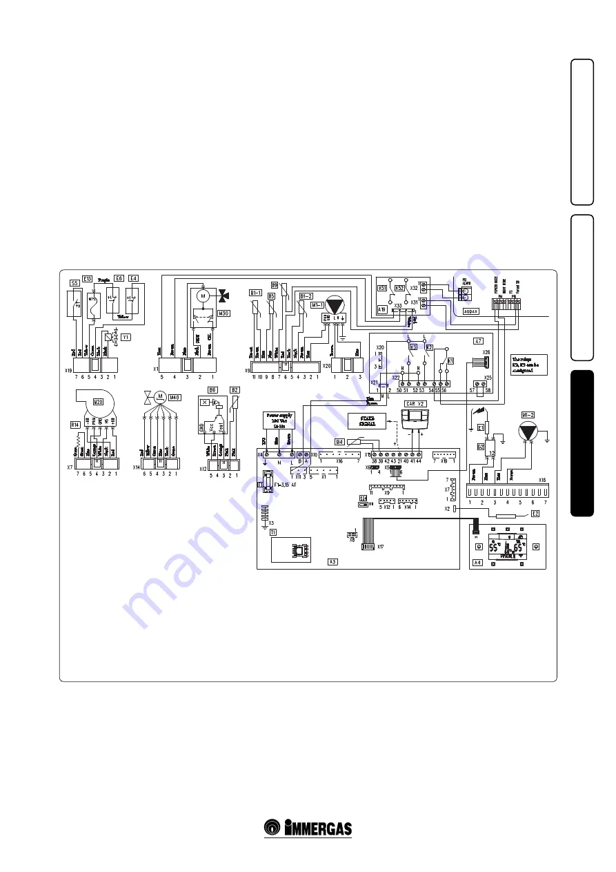
3.1  WIRING DIAGRAM.

The connector X6 is for connection to a personal 

computer.
The connector X8 is used for software updating 

operations.
Selector S34 defines boiler operation with the 

external probe and must always be set = On.


M30  -  Three-way valve


M40  -  Domestic flow rate regulator


S5  -  System pressure switch


S20  -  Room thermostat (optional)


S34  -  System supervisor connection 

selector 


R14  -  Boiler configuration resistance


T1  -  Low voltage power supply unit


Y1  -  Gas valve

Key:


A3  -  Integrated P.C.B


A4  -  Display board


A7  -  Relay P.C.B.


A19  -  Relay P.C.B. 2


B1-1  -  Boiler flow probe


B1-2  -  System flow probe


B2  -  Domestic hot water probe


B4  -  External probe 


B5  -  Return probe


B6  -  Domestic hot water flow meter


B9  -  Domestic hot water inlet probe

  CAR

V2

  -  Comando Amico Remoto remote 

control

V2


E1  -  Ignition electrodes


E2  -  Detection electrode


E4  -  Safety thermostat


E6  -  Flue safety thermostat


E13  -  Heat exchanger safety thermofuse


F1  -  Phase fuse


G2  -  Igniter


K1  -  Heating / cooling selector relay


K51  -  Stand-by / on forcing relay


K52  -  Anomaly relay


M1-1  -  Boiler circulator pump


M1-2  -  System circulator pump


M20  -  Fan

Yellow

Purple

Re

d

Gr

een

Gr

een

Bl

ue

Ora

ng

e

W

hi

te

Bl

ac

k

Re

d

Re

d

Ye

llo

w

G

re

en

G

re

en

Bl

ue

Bl

ue

Br

ow

n

Bl

ue

Bl

ac

k

Br

ow

n

Br

ow

n

Br

ow

n

Bl

ue

Bl

ue

W

hi

te

Re

d

Bl

ac

k

Bl

ac

k

Br

ow

n

Br

ow

n

Y/G

Bl

ue

Br

ow

n

Br

ow

n

Bl

ue

Bl

ue

Br

ow

n

Brown

Blue

Bl

ue

W

hi

te

Re

d

The relays 

K2, K3 can be 

configured

STATE  

SIGNAL

Power supply 

230 Vac  

50 Hz

Bl

ue

CH.

DHW

Bl

ac

k

W

hi

te

Br

ow

n

Ora

ng

e

Pin

k

Pin

k

Re

d

Ye

llo

w

G

re

en

Bl

ac

k

Bl

ac

k

Summary of Contents for MAGIS Victrix

Page 1: ...MAGIS Victrix IE Instruction and warning book 1 035518ENG ...

Page 2: ......

Page 3: ... or succession of ownership It must be stored with care and consulted carefully as all of the warnings provide important safety indications for installation use and maintenance stages This instructions manual provides technical information for installing Immergas boilers As for the other issues related to boiler installation e g safety in the work site environment protection injury prevention it i...

Page 4: ...instructions 22 2 1 Cleaning and maintenance 22 2 2 General warnings 22 2 3 Control panel 22 2 4 Description of functioning states 23 2 5 Using the boiler 24 2 6 Troubleshooting 25 2 7 Parameters and information menu 27 2 8 Boiler shutdown 28 2 9 Restoring central heating system pressure 28 2 10 System drainage 28 2 11 Anti freeze protection 28 2 12 Case cleaning 28 2 13 Decommissioning 28 3 Boile...

Page 5: ...tic polystyrene etc Do not place household appliances underneath the boiler as they could be damaged if the safety valve intervenes with an obstructed conveying system the safety valve must be conveyed away by a draining funnel or if there are leaks from the hydraulic connections on the contrary the manufacturer cannot be held responsible for any damage caused to the household appliances For the a...

Page 6: ...ary with respect to the minimum temperature at which the system must be kept An aqueous solution must be made with potential pollution class of water 2 The materials used for the central heating circuit of Immergas boilers withstand ethylene and propylene glycol based antifreeze liquids if the mixtures are prepared perfectly For life and possible disposal follow the supplier s instructions Protect...

Page 7: ...Telescopic fitting 3 4 R RHT MHT M N 1 Rubber fitting for condensate drainage SC N 1 Condensate drainage corrugated pipe SC N 1 Extension for filling valve N 1 Filling valve N 1 Condensation collection tray Gaskets screws and seal O Ring Key V Electrical connection G Gas supply AC Domesic hot water outlet AF Domestic cold water inlet SC Condensate drain minimum internal diameter Ø 13 mm VS Safety ...

Page 8: ...e making the boiler connections carefully wash the heating system pipes radiators etc with special pickling or descaling products to remove any deposits that could compromise correct boiler operation A chemical treatment of the thermal system water is required in compliance with the technical standards in force in order to protect the system and the appliance from deposits e g lime scale slurry or...

Page 9: ...larity and using the connection cable that comes out of the boiler and which is appropriately marked Fig 1 4 Connection with the wrong polarity prevents the CARV2 from operating although without damaging it The connection to the boiler is made using wires with a minimum section of 0 50 mm2 and maximum section of 2 5 mm2 and with a maximum length of 50 metres External temperature probe electrical c...

Page 10: ...e of Terminal Kit This information allows calculations to be made to verify the possibility of setting up various flue configurations Positioning the gaskets black for green range flue extraction systems Position the gasket correctly for bends and extensions Fig 1 6 gasket A with notches to use for bends gasket B without notches to use for extensions N B if component lubrication already carried ou...

Page 11: ...ntake and Exhaust 16 3 m 2 5 Intake m 18 7 Exhaust m 4 9 m 7 7 Exhaust m 13 6 Concentric vertical intake exhaust terminal Ø 60 100 Intake and Exhaust 9 m 1 4 Intake m 10 3 Exhaust m 2 7 m 4 3 Exhaust m 7 5 Pipe Ø 80 1 m Intake 0 87 m 0 1 Intake m 1 0 Exhaust m 0 4 m 0 4 m 0 5 Exhaust 1 2 m 0 2 Exhaust m 1 0 Complete intake terminal Ø 80 1 m Intake 3 m 0 5 Intake m 3 4 Exhaust m 0 9 m 1 4 Intake te...

Page 12: ... to block the 4 gasket flaps Fit the male end smooth of the exhaust terminal into the the female end of the bend 90 Ø 80 making sure that the relevant wall sealing plate is already fitted this will ensure hold and joining of the elements making up the kit Max length of exhaust duct The flue pipe both vertical or horizontal can be extended to a max length of 30 linear metres Coupling of extension p...

Page 13: ...ternal grid N B for proper system operation the terminal with grid must be installed correctly ensuring that the high indication on the terminal is observed during installation Horizontal intake exhaust kits Ø80 125 Kit assembly Fig 1 13 to install the kit Ø 80 125 one must use the flanged adapter kit in order to install the flue system Ø 80 125 Install the flanged adaptor 2 on the central hole of...

Page 14: ...take exhaust pipe 5 Fit the Ø 60 100 3 concentric terminal pipe with the male end 5 smooth into the flange 2 up to the stop making sure that the wall sealing plate has been fitted 3 this will ensure sealing and joining of the elements making up the kit Extensions for vertical kit Ø 60 100 Fig 1 16 The kit with this configuration can be extended to a max straight vertical length of 14 4 m including...

Page 15: ...ole with respect to the central one according to needs and replace it with the flange 3 positioning the gasket 2 already present in the boiler and tighten using the supplied self threading screws Fit the male end smooth to the bends 5 in the female end of the flanges 3 and 4 Fit the intake terminal 6 with the male section smooth in the female section of the bend 5 up to the stop ensuring that the ...

Page 16: ...ternal pipe must be fitted on the adaptor until it stops 1 N B to encourage the removal of possible condensate forming in the exhaust pipe tilt the pipes towards the boiler with a minimum slope of 1 5 Mount the cover A complete with adaptor 1 and caps 6 on the wall and assemble the flue system to the ducting system N B version Ø 125 only before assembly check the gaskets are in the right position ...

Page 17: ...ble tube inside the flue technical slot The maximum possible length of the Ø 80 rigid ducting vertical section is equal to 30 m This length is obtained considering the complete Ø 80 exhaust terminal 1m of Ø 80 pipe in exhaust two 90 Ø 80 bends on the boiler outlet 1 16 CONFIGURATION TYPE B23 OPEN CHAMBER AND FORCED DRAUGHT FOR INDOORS The appliance can be installed inside buildings in B23 mode in ...

Page 18: ... keeping the motor running Tighten the cap after the operation 1 20 CONDENSATE TRAP FILLING On first lighting of the boiler combustion products may come out the condensate drain after a few minutes operation check that this no longer occurs This means that the trap is filled with condensate to the correct level preventing the passage of combustion products 1 21 GAS SYSTEM START UP To start up the ...

Page 19: ...he selector switch clockwise in the relative power scale Proportional head program ΔP V 3 fig 1 26 This allows the pressure level head to be proportionally reduced as the system heat demand decreases flow rate reduction Thanks to this function the electric power consumption of the circulator pump is reduced further the energy power used by the pump decreases according to the pressure level and flo...

Page 20: ...functioning characteristics of the boiler thanks to its inspectionable filter Kit with two motorised areas on request In the event one wants to divide the thermal system in two areas to interlock them separately with independent adjustments on request Immergas can supply the kit with two motorised areas Polyphosphate dispenser kit on request The polyphosphate dispenser reduces the formation of lim...

Page 21: ...tion module 14 Manual air vent valve 15 Negative signal pressure point 16 Positive signal pressure point 17 Sample points air A flue gas F 18 Flue safety thermostat 19 Heat exchanger safety thermal fuse 20 System vent tank air valve 21 System vent tank 22 Ignition electrodes 23 Fan 24 Igniter 25 Burner 26 Return probe 27 System pressure switch 28 Vent valve 29 System probe 30 Boiler circulator pum...

Page 22: ...equires some fundamental rules to be observed do not touch the appliance with wet or moist parts of the body do not touch when barefoot never pull electrical cables or leave the appliance exposed to weathering rain sunlight etc the appliance power cable must not be replaced by the user in the event of damage to the cable switch off the appliance and contact exclusively qualified staff for replacem...

Page 23: ... in function after a request for domestic hot water or central heating in order to evacuate residual flue gases F5 Postcirculation in progress Pump in function after a request for domestic hot water or central heating in order to cool the primary circuit P33 With Remote Control in block the boiler works equally in central heating mode Can be activated through the M3 menu It allows to activate the ...

Page 24: ... the relative power scale and the indicator 9 and 7 with the instantaneous outlet temperature from the boiler During the heating stage if the water temperature is sufficient to heat the system the boiler can operate just with the activation of water circulation Room heating with heat pump during the request CH ON appears on the display 24 on the status indicator 6 and at the same time as the heat ...

Page 25: ...n of the boiler is not detected Check on the boiler pressure gauge 1 that the system pressure is between 1 1 2 bar and restore the correct pressure if necessary 15 Configuration error If the board detects an anomaly or incongruity on the electric wiring the boiler will not start If normal conditions are restored the boiler restarts without having to be reset 1 2 16 Fan anomaly This occurs if the f...

Page 26: ...eaches a temperature that is too high Make sure that water circulates properly in the boiler and that the three way valve works properly Press the Reset button 1 2 50 External probe missing or faulty In the event the external probe is not connected or is faulty the anomaly is indicated Check the external probe connection 1 3 58 Heat pump anomaly In the event of a heat pump anomaly room heating is ...

Page 27: ...e display is always lit up OFF The display only lights up when the controls are accessed and remains on for 5 seconds after the last operation performed P32 D C P32 B D C ITALIANO Default D x select C All descriptions are given in Italian A 1 All descriptions are given in alphanumerical format P33 D C OFF Default D x select C In winter mode by activating this function it is possible to activate th...

Page 28: ...s an anti freeze function that lights the burner automatically when the temperature falls below 4 C standard protection up to minimum temperature of 3 C All information relative to the anti freeze protection is stated in Par 1 3 In order to guarantee the integrity of the appliance and the domestic hot water heating system in zones where the temperature falls below zero we recommend the central hea...

Page 29: ...om where provided If even only a single safety check offers a negative result do not commission the system 3 1 WIRING DIAGRAM The connector X6 is for connection to a personal computer The connector X8 is used for software updating operations Selector S34 defines boiler operation with the external probe and must always be set On M30 Three way valve M40 Domestic flow rate regulator S5 System pressur...

Page 30: ...ssure point 22 Flue sample point 23 Fumes hood 24 Heat exchanger safety thermal fuse 25 Delivery probe 26 Safety thermostat 27 Ignition electrodes 28 Burner 29 Condensation module cover 30 Return probe 31 System expansion vessel 32 System draining valve 33 System pressure switch 34 DHW heat exchanger 35 Three way valve motorised 36 System vent tank air valve 37 3 bar safety valve 38 System vent ta...

Page 31: ...e water circulation in the system or blocked pump Check on the manometer that the system pressure is within established limits Check that the radiator valves are not closed and also the functionality of the pump Drain trap clogged This may be caused by dirt or combustion products deposited inside Check by means of the condensate drain cap that there are no residues of material blocking the flow of...

Page 32: ...acement of the circuit board air gas circuit components or in the case of installations with fume extraction systems with horizontal concentric pipe measuring more than 1 metre The boiler heat output is correlated to the length of the air intake and flue exhaust pipes This decreases with the increase of pipe length The boiler leaves the factory adjusted for minimum pipe length 1m It is therefore n...

Page 33: ...e heating selector switch to maximum turn it in a clockwise direction until 99 is seen on the display To have an exact value of CO2 in the flue gases the technician must insert the sampling probe to the bottom of the sample point then check that the CO2 value is that specified in the table otherwise adjust the screw 12 Fig 3 4 gas flow rate regulator To increase the CO2 value one must turn the adj...

Page 34: ...ment P66 by pressing C 25 C P66 B With the external probe present it defines the maximum flow temperature corresponding to operation with minimum external temperature see graph Fig 1 5 it can be set between 50 C and 85 C N B to continue one must confirm the parameter press D or exit adjustment P66 by pressing C 55 C P66 C With the external probe present it defines at which minimum external tempera...

Page 35: ...automatic functioning therefore with variable flow rate Open adjuster completely open therefore maximum flow rate available 09 L M 12 L M and 15 L M operation with defined flow AUTO RELAY 1 RELE1 0 Relay 1 not used RELE1 1 RELE1 1 Heat pump control relay it switches operation from heating to cooling RELE1 2 The relay signals the intervention of a boiler block Can be coupled to an external signalli...

Page 36: ...e event the boiler circulator pump is replaced with a traditional fixed speed circulator pump one must connect the new circulator pump to the relay board P76 15 C 14 C CE With S34 On If the reading of the external probe is not correct it is possible to correct it in order to compensate any environmental factors With S34 Off Setting not used 0 C MAGIS PAR 1 0 25 55 C Heat pump set point value durin...

Page 37: ...perate simultaneously in fact if only the heat pump is active but it cannot bring the water to temperature within a certain time the boiler starts in parallel The boiler electronics select which heat source to be used according to the combination of MAGIS parameters The heating mode is equipped with a timer that prevents the generators from restarting too frequently One can modify this value via p...

Page 38: ...t set by the domestic hot water selector switch SET the boiler does not switch on 3 18 YEARLY APPLIANCE CHECK AND MAINTENANCE The following checks and maintenance should be performed at least once a year Clean the flue side of the heat exchanger Clean the main burner If deposits are detected in the combustion chamber one must remove them and clean the exchanger coils using nylon or sorghum brushes...

Page 39: ...ng the two screws 11 disassemble the front 1 of the boiler by loosening the screw 2 by 1 4 turn push the front upwards while pulling it towards you at the same time to release it from the side 3 and upper 4 hooks undo the 2 screws 5 of the control panel 6 tilt the control panel 6 pulling it towards you see figure remove the sides 7 loosening the screws 8 push slightly upwards in order to release t...

Page 40: ...53 0 20 0 17200 2 16 3 48 35 5 1 61 3 40 34 7 1 58 4 54 46 3 19 0 16340 2 05 3 17 32 3 1 53 3 10 31 6 1 50 4 15 42 4 18 0 15480 1 94 2 87 29 3 1 45 2 81 28 6 1 42 3 79 38 7 17 0 14620 1 84 2 59 26 5 1 37 2 53 25 8 1 35 3 45 35 1 16 0 13760 1 73 2 33 23 8 1 29 2 28 23 2 1 27 3 12 31 8 15 0 12900 1 63 2 09 21 3 1 21 2 03 20 7 1 19 2 81 28 6 14 0 12040 1 52 1 85 18 9 1 13 1 81 18 4 1 12 2 51 25 6 13 ...

Page 41: ...Min 97 9 91 6 Efficiency 50 30 Nom Min 106 0 103 7 Efficiency 40 30 Nom Min 107 0 104 7 Heat loss at casing with burner On Off 80 60 C 0 61 0 80 Heat loss at flue with burner On Off 80 60 C 0 04 1 90 Central heating circuit max operating pressure bar 3 Central heating circuit max operating temperature C 90 Adjustable heating temperature max operation field C 20 85 System expansion vessel total vol...

Page 42: ......

Page 43: ......

Page 44: ...om Immergas S p A 42041 Brescello RE Italy T 39 0522 689011 F 39 0522 680617 The instruction handbook is printed on environmentally friendly paper Code 1 035518ENG rev 15 040050 000 03 2013 Inglese per IRLANDA IE ...

Reviews: