11
1-12
1-11
1-10
INS
TALLER
US
ER
MAINTEN
AN
CE TECHNI
CI
AN
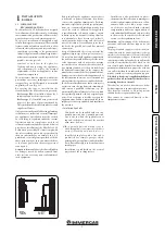
1.9 OUTDOOR INSTALLATION IN
PARTIALLY PROTECTED AREA.
N.B.:
a partially protected location is one in which
the appliance is not exposed to the direct action of
the weather (rain, snow, hail, etc..).
• Configuration type B, open chamber and
forced draught.
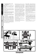
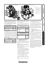
The relevant terminal must be used for this
configuration (present in the intake kit for the
installation in question), which must be placed
on the central hole of the boiler (Fig. 1-12). Air
intake takes place directly from the room where
the boiler is installed and flue exhaust in an in-
dividual flue or directly to the outside.
Boiler with this type of configuration are classi-
fied as type B
22
.
With this configuration:
- air intake takes place directly from the envi-
ronment in which the appliance is installed
(external);
- the flue exhaust must be connected to its own
individual flue or channelled directly into the
external atmosphere.
Accordingly, technical standards in force must
be observed.
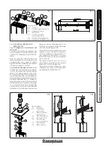
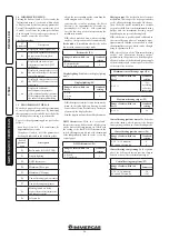
Max. length of exhaust duct.
The flue pipe
(vertical or horizontal) can be extended to a max.
length of 12 linear metres, using insulated pipes
(Fig. 1-28) and limit the length of the Ø 80 normal
flue pipe (not insulated) to just 5 metres.
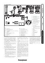
Example of installation with direct vertical
terminal in partially protected location.
When
the vertical terminal for direct discharge of com-
bustion fumes is used, a minimum gap of 300 mm
must be left between the terminal and the balcony
above. The height X+Y+Z+W evaluated with
respect to the balcony above, must be equal to
or more than 2000 mm. (Fig. 1-11). The term W
must only be considered if the balcony above has
closed balustrade (W=0 if the balustrade is open).
• Configuration without cover kit
(boiler type C).
By leaving the side plugs fitted, it is possible to
install the appliance externally, in partially co-
vered places, without the cover kit. Installation
takes place using the Ø60/100 and Ø80/125
concentric horizontal intake/ exhaust kits. Refer
to the paragraph relative to indoor installation. In
this configuration the upper cover kit guarantees
additional protection for the boiler. It is recom-
mended but not compulsory.
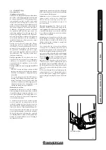
• Fitting the cover kit.
To assemble and confi-
gure the cover kit correctly, please refer to the
relative instructions sheet.
VERTICAL TERMINAL KIT FOR
DIRECT DRAINING
INTAKE COVER KIT
Summary of Contents for MINI EOLO 24 3E
Page 1: ...MINI EOLO 24 3E Instruction and warning book 1 038773ENG ...
Page 2: ......
Page 28: ...28 3 5 4 4 5 6 6 d d c INSTALLER USER MAINTENANCE TECHNICIAN ...
Page 33: ...33 ...
Page 34: ...34 ...
Page 35: ...35 ...


