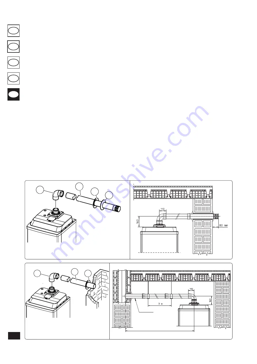
Ø 80 horizontal kit with wall flue exhaust.
Kit assembly (Fig. 1-18): install the bend Ø 80 (1)
with the male side (smooth) fully home on the
central hole of the boiler. Fit the exhaust terminal
(2) with the male end (smooth) to the female
end of the bend (1) up to the stop; making sure
that the internal (3) and external (4) wall sealing
plate has been fitted. This will ensure sealing and
joining of the elements making up the kit.
• Coupling of extension pipes and elbows. To
install push-fitting extensions with other ele-
ments of the flue extraction elements assembly,
proceed as follows: engage the pipe or elbow
with the male side (smooth) in the female
section (with lip seal) up to the stop on the
previously installed element. This will ensure
sealing efficiency of the coupling.
Horizontal kit Ø 80 with exhaust in flue.
Kit
assembly (Fig. 1-20): install the bend Ø 80 (1)
with the male side (smooth) fully home on the
central hole of the boiler. Fit the exhaust pipe (2)
with the male end (smooth) to the female end of
the bend (1) up to the stop; making sure that the
internal wall sealing plate has been fitted (3). This
will ensure sealing and joining of the elements
making up the kit.
• Coupling of extension pipes and elbows. To
install push-fitting extensions with other ele-
ments of the flue extraction elements assembly,
proceed as follows: engage the pipe or elbow
with the male side (smooth) in the female
section (with lip seal) up to the stop on the
previously installed element. This will ensure
sealing efficiency of the coupling.
• Extensions for exhaust kits. The maximum
The kit includes:
N° 1 - Bend 90° Ø 80 (1)
N° 1 - Exhaust pipe Ø 80 (2)
N° 1 - Internal wall sealing plate (3)
horizontal straight length (without bend in
exhaust), used for Ø 80 exhaust pipes is
14,5
metres
(Fig. 1-21).
N.B.:
to favour the removal of possible conden-
sate forming in the exhaust pipe, tilt the pipes
towards the boiler with a min. slope of 1.5%.
When installing the Ø 80 ducts, a section clamp
with pin must be installed every 3 metres.
1.12 DUCTING OF ExISTING FLUES.
Ducting is an operation through which, within
the context of restructuring a system and with the
introduction of one or more special ducts, a new
system is executed for evacuating the combustion
products of a gas appliance, starting from an
existing flue (or a chimney) or a technical hole.
Ducting requires the use of ducts declared to be
suitable for the purpose by the manufacturer.
Follow the installation and user instructions
provided by the manufacturer and the require-
ments of standards.
Immergas ducting system Ø 80.
The “Green
Series” Ø 80 flexible ducting system must only be
used with Immergas condensing boilers.
In any case, ducting operations must respect
the provisions contained in the standard and in
current technical regulations; in particular, the
declaration of conformity must be compiled at
the end of work and on commissioning of the
ducted system. The instructions in the project
or technical report must likewise be followed, in
cases provided for by the standard and current
technical regulations. The system or components
of the system have a technical life complying with
current standards, provided that:
- it is used in average atmospheric and envi-
ronmental conditions, according to current
regulations (absence of fumes, dusts or gases
that can alter the normal thermophysical or
chemical conditions; existence of temperatu-
res coming within the standard range of daily
variation, etc.).
- Installation and maintenance must be perfor-
med according to the indications supplied by
the manufacturer and in compliance with the
provisions in force.
- The maximum length of that the Ø 80 flexible
ducted tract can run
is equal to 17 m
. This
length is obtained considering the terminal
complete with exhaust 1m of Ø 80 pipe in
exhaust. The two 90° Ø 80 bends on boiler
outlet for connecting the ducting system and
two direction changes of the flexible pipe inside
the chimney/technical hole.
Fig. 1-18
Fig. 1-19
B23
Fig. 1-20
B23
B23
Fig. 1-21
1
4
3
2
SCARICO
1
3
2
SCARICO
The kit includes:
N° 1 - Bend 90° Ø 80 (1)
N° 1 - Exhaust terminal Ø 80
(2)
N° 1 - Internal wall sealing
plate (3)
N° 1 - External wall sealing
plate (4)
B23
min. 1,5%
MAXIM
UM LENGHT 14,5 m
122
TR
SI
RU
IE
CZ


