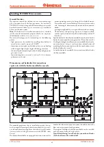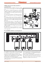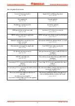
44
STV50 ed 09/08
VICTRIX 50 Rev. 002
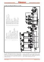
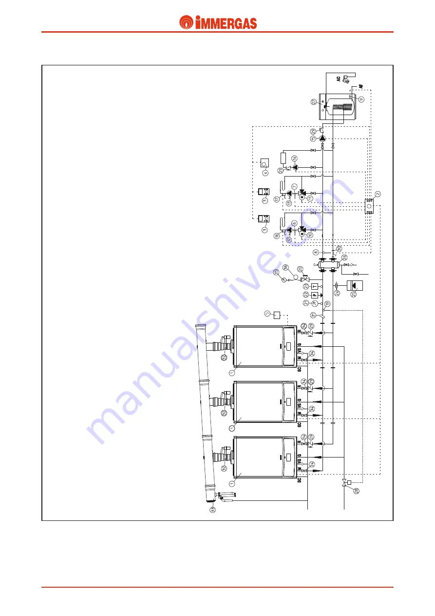
Legend:
1
-
VICTRIX 50 gener
ator
2
-
C
ascade and z
one r
egulator
3
-
Zone r
egulator
4
-
M
odulating r
oom ther
mostat
5
-
Exter
nal pr
obe
6
-
N
o.1 z
one temper
atur
e pr
obe (CMI-1)
7
-
N
o. 2 z
one temper
atur
e pr
obe (CMI-2)
8
-
Shar
ed deliv
er
y pr
obe
9
-
W
ater tank temper
atur
e pr
obe
10
-
N
o.1 z
one mixing v
alv
e (CMI-1)
11
-
N
o. 2 z
one mixing v
alv
e (CMI-2)
12
-
N
o.1 z
one centr
al heating cir
cuit pump (CMI-1)
13
-
N
o. 2 z
one centr
al heating cir
cuit pump (CMI-2)
14
-
N
o. 3 z
one dir
ect cir
cuit pump (HC)
15
-
W
ater tank supply pump
16
-
N
o.1 z
one safety ther
mostat (CMI-1)
17
-
N
o.2 z
one safety ther
mostat (CMI-2)
ZONE 1 (MC 1)
ZONE 2 (MC 2)
ZONE 3
(HC)
19
-
O
n-off fuel v
alv
e bulb
20
-
ISP
ESL appr
ov
ed cock with pr
essur
e gauge
21
-
ISP
ESL appr
ov
ed ther
mometer
22
-
ISP
ESL appr
ov
ed manual r
eset pr
essur
e switch
23
-
ISP
ESL appr
ov
ed manual r
eset ther
mostat
24
-
Expansion v
essel coupling
25
-
Expansion v
essel
26
-
M
anifold/mixing device
27
-
Exter
nal water tank unit
28
-
Fuel on-off v
alv
e
29
-
O
n-way v
alv
e
30
-
Sludge collecting system filter
31
-
Ther
mometer holding pocket
32
-
Flue str
eam adjusting device
33
-
Condensate dr
ain pipe
34
-
System on-off cock
35
-
ISP
ESL appr
ov
ed manometer
36
-
W
ater hammer r
educing loop
Example of installing VICTRIX 50 in a cascade.
The above example refers to three boilers installed in a cascade,
equipped with an ISPESL safety kit and a mixing manifold
(26). The system consists of two, low temperature mixed zones,
a high temperature zone and a storage tank for the production
of domestic hot water.
The system is controlled by a cascade regulator (2) that controls
the storage tank directly, two zone managers (3) that control the
two low-temperature zones and a modulating room thermostat
(4) that controls the high temperature zone.
Technical Documentation
Technical Documentation


