background image

18

1-27

INS

T

ALLER

US

ER

MAINTEN

AN

CE TECHNI

CI

AN

1.20  WATER TREATMENT SYSTEM 

FILLING.

As  already  mentioned  in  the  previous  para-
graphs,  a  chemical  treatment  of  the  thermal 
system water is required, in compliance with the 
local standards in force.

The parameters that influence the duration and 
proper operation of the heat exchanger are the 
water's PH, hardness, conductivity, and oxygen, 
together  with  the  system's  processing  residues 
(any welding residues), any oil present and cor-
rosion products that can, in turn, cause damage 
to the heat exchanger. 

In order to prevent this from happening, you are 
recommended to:
-  Before installation on new systems as well as 

old ones, clean the system with clean water to 
eliminate solid residues contained therein.

-  Clean the system with a chemical treatment:

  -  Clean the new system with a suitable cleaning 

device  (for  example  Sentinel  X300,  Fernox 
Cleaner F3 or Jenaqua 300) combined with 
thorough washing.

  -  Clean the old system with a suitable cleaning 

device (for example Sentinel X400 or X800, 
Fernox Cleaner F3 or Jenaqua 400) combined 
with thorough washing.

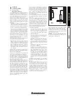
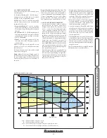
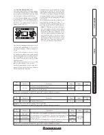
-  Check  the  maximum  hardness  and  quantity 

of filling water referring to the graphics (Fig. 
1-27). If the contents and hardness of the water 
are below the indicated curve, no specific treat-
ment is required; otherwise, to limit the content 
of  calcium  carbonate,  you  must  provide  for 
water-filling treatment. 

-  For  filling,  you  are  not  allowed  to  use  water 

softened with the use of ionic-exchange resins 
or distilled water.

-  Should  you  be  required  to  provide  for  water 

treatment,  this  should  be  carried  out  by 
completely  desalinating  the  filling  water.  As 
opposed  to  the  complete  softening  process, 
desalinating  the  water  completely  not  only 
removes hardening agents (Ca, Mg), but also 
eliminates all other minerals to reduce water-
filling  conductivity  up  to  10  microsiemens/
cm.  Given  its  low  conductivity,  desalinated 
water does not only prevent the formation of 
lime scale, but also serves as protection against 
corrosion.

-  Insert  a  suitable  inhibitor  /  passivator  (for 

example  Sentinel  X100,  Fernot  Protector  F1, 
or Jenaqua 100); if required, also insert appro-
priate antifreeze (such as for example Sentinel 
X500, Fernox Alphi 11 or Jenaqua 500).

-  Check electrical conduction of the water, which 

should be higher than 2000 

µ

s/cm in the case 

of treated water and lower than 600 

µ

s/cm in 

the case of non-treated water.

-  To  prevent  corrosion,  the  water  system's  PH 

should be between 6.5 and 8.5.

-  Check  the  maximum  content  of  chlorides, 

which should be less than 250 mg/l.

N.B.:

 for quantities and methods of use of water-

treatment  products,  refer  to  the  instructions 
provided by their manufacturer.

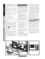
1.21  SYSTEM FILLING.

Once  the  boiler  is  connected,  proceed  with 
system filling via the filling cock (Fig. 1-29 and 
1-3). Filling is performed at low speed to ensure 
release of air bubbles in the water via the boiler 
and heating system vents.
The  boiler  has  a  built-in  automatic  venting  valve 
on the circulator. 

Check if the cap is loose.

 Open the 

radiator vent valves.
Close  radiator  vent  valves  when  only  water 
escapes from them.
Close the filling cock when the boiler pressure 
gauge indicates approx. 1.2 bar. 

N.B.:

  during  these  operations,  enable  the  au-

tomatic vent functions on the boiler (active on 
first ignition). 

1.22  CONDENSATE TRAP FILLING.

On first lighting of the boiler, flue gas may come 
out  the  condensate  drain;  after  a  few  minutes’ 
operation check that this no longer occurs. This 
means that the drain trap is filled with conden-
sate to the correct level preventing the passage 
of flue gas.

1.23  GAS SYSTEM START

-

UP.

To  start  up  the  system,  refer  to  the  technical 
standard in force: This divides the systems and 
therefore  the  start-up  operations  into  three 
categories:  new  systems,  modified  systems,  re-
activated systems. 
In particular, for new gas systems:
-  open windows and doors;

-  avoid presence of sparks or open flames;

-  bleed all air from the pipelines;

-  check that the internal system is properly sealed 

according  to  the  specifications  set  forth  by 
technical regulations in force.

1.24  BOILER START UP 

(

IGNITION

)

.

In order to issue the Declaration of Conformity 
required by the laws in force, the following re-
quirements must be fulfilled to commission the 
boiler (the operations listed below must only be 
performed by a qualified firm and without any 
unauthorised persons):
-  check that the internal system is properly sealed 

according  to  the  specifications  set  forth  by 
technical regulations in force;

-  ensure that the type of gas used corresponds to 

the boiler settings (the type of gas appears on 
the display on first electrical supply voltage, or 
by checking the relative parameter “G”);

-  check  connection  to  a  230V-50Hz  power 

mains, correct L-N polarity and earthing con-
nection;

-  check that there are external factors that may 

cause the formation of fuel pockets; 

-  switch the boiler on and check correct ignition;

-  make sure that the gas flow rate and relevant 

pressure values comply with those given in the 
manual (Par. 3.22);

-  ensure that the safety device intervenes in the 

event of gas supply failure and check the relative 
intervention time;

-  check  the  intervention  of  the  main  switch 

located  upstream  from  the  boiler  and  in  the 
boiler;

-  check that the intake/exhaust concentric ter-

minal (if fitted) is not blocked.

-  Carry  out  the  flue  test  and  set  the  relative 

parameter "F0".

The boiler must not be started up even if only 
one of the checks should be negative.

N.B.:

  only  upon  completing  commissioning  by 

an installer, may an authorised firm carry out an 
initial inspection of the boiler, which is required to 
activate the Immergas warranty. The test certificate 
and warranty is issued to the user.

N.B.:

 the graph refers to the 

entire life cycle of the system. 
Therefore, also consider sched-
uled and unscheduled mainte-
nance, which involves emptying 
and filling the said system.

Water hardness °F

Sys

tem w

at

er l

it

re

s

Summary of Contents for VICTRIX MAIOR 28 - 35 TT 1 ERP

Page 1: ...VICTRIX MAIOR 35 X TT 1 ERP IE Instruction and recommendation booklet 1 038660ENG...

Page 2: ......

Page 3: ...ned by qualified professionals within the dimensional limits established by the Law Installation and maintenance must be performed in compliance with the regulations in force according to the manufact...

Page 4: ...2 General warnings 21 2 3 Control panel 21 2 4 Using the boiler 22 2 5 Troubleshooting 22 2 6 Information menu 25 2 7 Boiler shutdown 25 2 8 Restore central heating system pressure 25 2 9 System drain...

Page 5: ...ance paper rags plastic polystyrene etc Do not place household appliances underneath the boiler as they could be damaged if the safety valve intervenes if the drain trap is blocked or if there are lea...

Page 6: ...ary with respect to the minimum temperature at which the system must be kept An aqueous solution must be made with potential pollution class of water 2 EN 1717 2002 The materials used for the central...

Page 7: ...descaling products to remove any deposits that could compromise correct boiler operation A chemical treatment of the thermal system water is required in compliance with the tech nical standards in fo...

Page 8: ...hermostats are connected with 2 wires only Carefully read the user and assembly instructions contained in the acces sory kit On Off Immergas digital chrono thermostat The chrono thermostat allows set...

Page 9: ...s the max system flow temperature to be automatically decreased when the external temperature increases in order to adjust the heat supplied to the system according to the change in external temperatu...

Page 10: ...ds to the resistance encountered with the maximum allowed pipe length for each type of Terminal Kit This information allows calculations to be made to verify the possibility of setting up various flue...

Page 11: ...Intake and Exhaust 16 3 m 2 5 Intake m 18 7 Exhaust m 4 9 m 7 7 Exhaust m 13 6 Concentric vertical intake exhaust terminal 60 100 Intake and Exhaust 9 m 1 4 Intake m 10 3 Exhaust m 2 7 m 4 3 Exhaust m...

Page 12: ...side using the 2 previously removed screws Install the 80 outlet flange on the central hole of the boiler taking care to insert the gasket supplied with the kit and tighten by means of the screws prov...

Page 13: ...th the circular projections down wards in contact with the boiler flange and tighten using the screws present in the kit Fit the 60 100 3 concentric terminal pipe with the male side smooth to the fema...

Page 14: ...nge 2 up to the end stop making sure that the wall sealing plate has been fitted 3 this will ensure sealing and joining of the elements making up the kit NOTE when the boiler is installed in areas whe...

Page 15: ...the flat flange present in the lateral hole with respect to the central one ac cording to needs and replace it with the flange 3 positioningthegasket 2 alreadypresentin the boiler and tighten using t...

Page 16: ...ical data The dimensions of the shafts must ensure a minimum gap between the outer wall of the smoke duct and the inner wall of the shaft 30 mm for circular section shafts and 20 mm in the event of a...

Page 17: ...mber boilers must not be installed in places where commercial artisan or industrial activities take place which use products that may develop volatile vapours or substances e g acid vapours glues pain...

Page 18: ...of air bubbles in the water via the boiler and heating system vents The boiler has a built in automatic venting valve on the circulator Check if the cap is loose Open the radiator vent valves Close r...

Page 19: ...hut off valve kits with or without inspection filter on request The boiler is designed for installation of system interception cocks to be placed on flow and return pipes of the connection assembly Th...

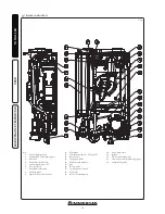
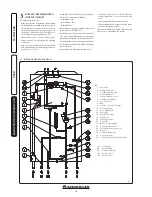
Page 20: ...s mixer 7 Manual air vent valve 8 Delivery probe 9 Ignition detection electrode 10 Flue probe 11 Sample points air A flue gas F 12 Burner cover 13 Safety flow probe 14 Condensation module 15 Fan 16 Re...

Page 21: ...ler to direct vapours from a cooking surface Use of the boiler by unskilled persons or children is strictly prohibited For safety purposes check that the concentric air intake flue exhaust terminal if...

Page 22: ...he boiler selecting a value from 0 to 9 With external probe present the relative symbol 18 will appear on the display In the central heating phase if the temperature of the water contained in the syst...

Page 23: ...ner flame switches off unexpectedly a new attempt at ignition is performed and if normal conditions are restored the boiler does not have to be reset If normal conditions are restored the boiler resta...

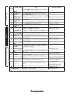
Page 24: ...as valve has been detected The boiler does not start 1 88 Block gas valve control A malfunction of one of the components that controls the gas valve has been detected The boiler does not start 1 89 Co...

Page 25: ...ned frequently filling must be car ried out with suitably treated water to eliminate hardness that can cause lime scale 2 11 CASE CLEANING Use damp cloths and neutral detergent to clean the boiler cas...

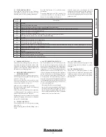
Page 26: ...he intervention of the main switch lo cated upstream of the boiler and in the boiler check that the intake and or exhaust terminals are not blocked ensure activation of all adjustment devices check th...

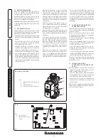
Page 27: ...connector X5 is used for the connection to the relay board The connector X6 is for connection to a personal computer The connector X8 is used for software updating operations Key A19 Removable memory...

Page 28: ...values are within the set limits The factory set pressure values of the expansion vessel must be 1 0 bar the value of system pressure must be between 1 and 1 2 bar Noise due to air inside the condens...

Page 29: ...o clock position Fig 3 5 and press the Reset button for about 8 seconds until the chimney sweep function is activated then press the summer winter button within 3 seconds Nominalheatoutput with the f...

Page 30: ...ction is activated then press the info button within 3 seconds Once the function is active the boiler sequential ly carries out the procedures required to calibrate the appliance with the nominal inte...

Page 31: ...anomaly E62 will appear and complete calibration will be required Menu G This menu is reserved for the air gas control settings and it features two sub menus n and S relating to fan and gas valve con...

Page 32: ...Off 1 General alarm 2 CH phase active 3 External gas valve power supply 4 Secondary zone control from TA on relay P C B contact 5 Heat pump 6 Do not use on this boiler model 7 Do not use on this boile...

Page 33: ...f 0 3 On 5 C Off 0 C 2 t3 Not used on this boiler model t4 Not used on this boiler model t5 Central heating ignitions timer The boiler has electronic timing which prevents the burner from igniting too...

Page 34: ...so as to reduce the risk of the three way group becoming blocked due to prolonged inactivity 3 17 RADIATORS ANTI FREEZE FUNCTION If the system return water is below 4 C the boiler starts up until reac...

Page 35: ...ionandintegrityoftheelectri cal system and in particular supply voltage cables must be inside the fairleads there must be no traces of blackening or burning Check ignition and operation Check correct...

Page 36: ...o screws a 2 Press the hooks inwards which block the lower grid b 3 remove the grid b Front panel Fig 3 15b 4 Open the protection door e1 pulling it towards you 5 Remove the cover caps c and loosen sc...

Page 37: ...STALLER USER MAINTENANCE TECHNICIAN Ref X Control panel Fig 3 15d 9 Press the hooks on the side of the control panel i 10 Tilt the control panel i towards you Sides Fig 3 15e 11 Loosen screws k of sid...

Page 38: ...tput C 47 47 METHANE G20 PROPANE G31 THERMAL POWER THERMAL POWER MODULATION BURNER GAS FLOW RATE BURNER GAS FLOW RATE kW kcal h m3 h kg h 34 2 29412 99 3 70 2 71 33 5 28810 97 3 62 2 66 32 5 27950 94...

Page 39: ...30 Nom Min 106 0 107 6 Casing losses with burner On Off 80 60 C 0 35 0 10 Heat loss at flue with burner On Off 80 60 C 0 01 2 00 Central heating circuit max operating pressure bar 3 0 Maximum heating...

Page 40: ...N Serial Number CHK Check Cod PIN PIN code Type Type of installation ref CEN TR 1749 Qnw min Minimum DHW heat input Qn min CH minimum heat input Qnw max DHW maximum heat input Qn max CH maximum heat i...

Page 41: ...y 0 072 kW At partial load elmin 0 012 kW Ignition burner energy consumption Pign 0 000 kW In standby mode PSB 0 006 kW Emissions of nitrogen oxides NOX 23 mg kWh For mixed central heating appliances...

Page 42: ...I FLHQF RI ERLOHU 1 7HPSHUDWXUH FRQWURO URP FKH RI WHPSHUDWXUH FRQWURO 6XSSOHPHQWDU ERLOHU URP FKH RI ERLOHU 6XSSOHPHQWDU KHDW SXPS URP FKH RI KHDW SXPS 6RODU FRQWULEXWLRQ DQG 6XSSOHPHQWDU KHDW SXPS 6...

Page 43: ...PHQWDU KHDW SXPS LQVWDOOHG ZLWK ORZ WHPSHUDWXUH KHDW HPLWWHUV DW URP FKH RI KHDW SXPS 7KH HQHUJ HI FLHQF RI WKH SDFNDJH RI SURGXFWV SURYLGHG IDU LQ WKLV FKH PD QRW FRUUHVSRQG WR LWV DFWXDO HQHUJ HI FL...

Page 44: ...GHU DQG ZDUPHU FOLPDWH FRQGLWLRQV ROGHU DUPHU HFODUHG ORDG SUR OH 6RODU FRQWULEXWLRQ URP FKH RI VRODU GHYLFH 1 2 X LOLDU HOHFWULFLW 3 G F E D C B A A A A M L XL XXL 3 2 3 2 7KH HQHUJ HI FLHQF RI WKH S...

Page 45: ...DWLQJ HQHUJ HI FLHQF FODVV RI SDFNDJH XQGHU DYHUDJH FOLPDWH DWHU KHDWLQJ HQHUJ HI FLHQF XQGHU FROGHU DQG ZDUPHU FOLPDWH FRQGLWLRQV ROGHU DUPHU HFODUHG ORDG SUR OH 6RODU FRQWULEXWLRQ URP FKH RI VRODU G...

Page 46: ...46...

Page 47: ...47...

Page 48: ...mmergas com Immergas S p A 42041 Brescello RE Italy Tel 0522 689011 Fax 0522 680617 Certified company ISO 9001 This instruction booklet is made of ecological paper Cod 1 038660ENG rev ST 001863 000 06...

Reviews: