45
INS
TALLER
U
SER
M
AINTEN
AN
CE
TECHNI
CI
AN
TECHNI
CAL
D
AT
A
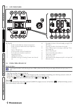
1.29 UPM3 CIRCULATION PUMP
During central heating mode, the Auto and Fixed operating modes are available.
-
Auto (A5 = 0):
automatic circulator pump speed and proportional head: the circulator pump speed varies according to the power sup-
plied by the burner, the greater the power the greater the speed. Moreover, within the parameter, one can also adjust the circulator
pump operating range by setting the maximum speed “A3” parameter (adjustable from 6 to 9) and the “A4” minimum speed parameter
(adjustable from 6 to max set speed).
-
∆T Constant (A5 = 5 ÷ 25 K):
the pump speed varies to maintain the ∆T constant between the system flow and return according to set
value K
(A5 = 15 Default).
-
Fixed (6 ÷ 9):
by setting parameters “A3” and “A4” at the same value, the pump operates at constant speed.
For the appliance to work properly, it is not allowed to drop below the minimum speed value.
In domestic hot water mode, the circulator pump always runs at full speed.
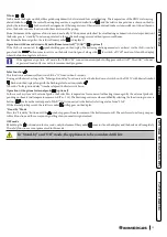
Pump LED.
The LED flashes green when the pump is powered and the pwm control signal is connected.
The LED lights up steady green when the pump is powered and the signal cable disconnected. In these conditions the pump
works at maximum and without control.
Alarm warnings.
If the pump detects an alarm, the LED switches from green to red; this can mean one of the following failures:
- low supply voltage;
- rotor seized;
- electrical error.
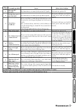
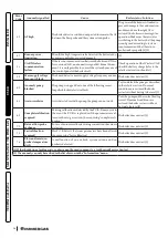
For a detailed description of the meaning of the red LED, refer to Paragraph 3.6.
The LED, in addition to being green or red, can also remain off.
It is normal for the LED to be off when the pump is not powered, whereas with the pump powered, the LED must be lit: if
switched off, it means there is a fault.
Pump release.
If after a long period of inactivity, the circulator is blocked, adjust the screw in the centre of the head in order to manually release the mo-
tor shaft.
Take great care during this operation to avoid damage to the motor.
Bypass Adjustment (Parag. 1.32).
The appliance leaves the factory with the bypass open.
If necessary, the by-pass can be regulated to system requirements from minimum (by-pass closed) to maximum (by-pass open).
Adjust using a flat head screwdriver, turn clockwise and open the by-pass, anticlockwise it is closed.
The bypass ensures minimum circulation of the water in the appliance and its correct operation if the systems are divided into
more than one zone.


