29
3-3
3
2
1
1
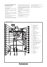
The jumper X40 must be removed when the
Room thermostat is connected; in addition, the
cascade regulator; in addition, it must be elim-
inated also in case of connection on the “M-O”
terminals or when the 0 ÷ 10 V inlet is used.
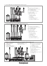
A thermostat can be used instead of “B2” (set
P29 = 17).
Set the corresponding parameters in case of con-
nection in “simple cascade”, or if connecting to
“Central heating NTC probe” or “DHW PUMP”.
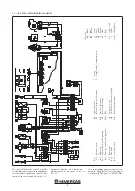
3.3 VERY LOW VOLTAGE WIRING DIAGRAM.
Ke
y:
A
2
-
Ele
ct
ro
nic
boa
rd
A4
-
D
isp
la
y b
oa
rd
B1
-
Fl
ow p
ro
be
B1-2
-
Sys
tem s
id
e fl
ow p
ro
be (o
pt
io
na
l)
B2
-
D
om
es
tic h
ot w
at
er p
ro
be (o
pt
io
na
l)
B4
-
Ext
er
na
l t
em
per
at
ur
e p
ro
be (o
pt
io
na
l)
B5
-
Re
tu
rn p
ro
be
B10
-
Fl
ue
pr
ob
e
B25
-
Sys
tem fl
ow m
et
er
E4
-
Sa
fety t
her
m
os
ta
t
E5
-
-H
ea
t-ex
ch
an
ger s
af
ety t
her
m
os
ta
t
(m
an
ua
l r
es
et)
E13
-
Fl
ue s
af
ety t
her
m
of
us
e
M1
-
Bo
iler ci
rcu
la
to
r p
um
p
M20
-
Fa
n
S5
-
Sys
tem p
re
ssu
re s
w
itc
h
S6
-
Ai
r p
re
ssu
re s
w
itc
h
S20
-
O
N/O
FF r
oo
m t
her
m
os
ta
t (o
pt
io
na
l)
X40
-
Ro
om t
her
m
os
ta
t j
um
per
1
-
Te
sting
2
-
“S
im
pl
e c
as
ca
de
” c
om
m
un
ica
tio
n b
us
3
-
0 - 10 V a
na
log
ue i
np
ut
Col
ou
r k
ey
:
BK
-
Bl
ac
k
BL
-
Bl
ue
BR
-
Br
ow
n
G
-
Gr
een
GY
-
Gr
ey
O
R
-
O
ra
nge
P
-
Pu
rp
le
PK
-
Pin
k
R
-
Re
d
Y
-
Ye
llo
w
Y/G
-
Ye
llo
w / G
re
en
W
-
W
hi
te
W/BK
-
W
hi
te / B
la
ck
Summary of Contents for VICTRIX PRO 35 2ErP
Page 1: ...IE Instruction and warning book VICTRIX PRO 35 55 2 ErP 1 041662ENG...
Page 2: ......
Page 38: ...38 3 15 1 6 8 9 9 12 12 10 11 13 13 13 13 A A Rif A 7 7 Ref A...
Page 49: ...49...
Page 50: ...50...
Page 51: ...51...


