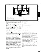
3.9 Air/gas ratio adjustment Victrix 20 boiler.
CO
2
setting. Switch the boiler on and bring it to “chimney
sweep” phase, ensuring that the heating power trimmer
(8 page 28) is at min. (turn it anticlockwise). To have an
exact value of CO
2
in the fumes the technician must insert the
sampling probe all the way in the chamber, then check that
the CO
2
value is that specified in the table, otherwise adjust
the CO
2
by means of screw (3) (Off-Set regulator) bringing
it to the value given in the table below. After making this
adjustment bring the heating power trimmer (8 page 28) to
max. and check maintaining of the CO
2
parameter.
CO
2
at rated
output
CO
2
at min.
output
G 20
9.2% ± 0.2
9% ± 0.2
G 30
12.5% ± 0.2
11.9% ± 0.2
G 31
10.6% ± 0.2
9.7% ± 0.2
3.10 Air-gas ratio adjustment Victrix 27 boiler.
Min. CO
2
setting.
Switch the boiler on and bring it to “chimney sweep” phase,
ensuring that the heating power trimmer (8) is at min. (turn
it fully anticlockwise). To have an exact value of CO
2
in the
fumes the technician must insert the sampling probe all the
way in the chamber, then check that the CO
2
value is that
specified in the table, otherwise adjust the screw (3 page 28)
(Off-Set regulator).
Max. CO
2
setting.
After min. CO
2
adjustment, switch the boiler on and bring
it to “chimney sweep” phase, ensuring that the heating power
trimmer (8) is at max. (turn it fully clockwise). To have an
exact value of CO
2
in the fumes the technician must insert
the sampling probe all the way in the chamber, then check
that the CO
2
value is that specified in the table, otherwise
adjust the screw (12 page 29) (gas flow regulator).
To increase the CO
2
value turn the adjustment screw (12)
anticlockwise or clockwise to decrease the value.
With every adjustment of screw 12 it is necessary to wait for
the boiler to stabilize at the set value (approx. 30 sec.).
CO
2
at rated
output
CO
2
at min.
output
G 20
9.44% ± 0.2
8.90% ± 0.2
G 30
12.2% ± 0.2
11.5% ± 0.2
G 31
10.35% ± 0.2
10.0% ± 0.2
3.11 Combustion parameters check.
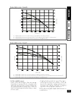
For max. and min. heat output adjustment insert the
differential manometer between P1 and P2 (see fig. on
page 23-24) for measuring the gas pressure. Bring the
boiler to “chimney sweep” phase, ensuring that the heating
power trimmer is at max. Adjust the max. fan speed
trimmer (9 page 28) in order to obtain (with burner on)
the value given in the table on page 32. In this way the
max. heat output adjustment is made. Turn the trimmer
clockwise to increase pressure and anticlockwise to
decrease the pressure.
e min. setting occurs automatically.
3.12 Adjustment of boiler rated heating power.
e Victrix boiler is produced with heat output in heating set
to max. erefore it is advisable not to change that setting.
If the heating power has to be reduced, the trimmer (8 page
28) must be adjusted. Turn the trimmer clockwise to increase
pressure and anticlockwise to decrease the pressure.
3.13 Circulating pump operation.
By operating the jumper (4 page 28) two circulating pump
operational modes can be selected in heating phase.
With the jumper present, circulating pump operation is
activated by the room thermostat or the Remote Friend
Control; with the jumper not present the circulating pump
always stays on.
3.14 “Chimney Sweep” function.
When activated, this function forces the boiler at max. heat-
ing power for 15 minutes.
In this mode all the adjustments are cut out and only the
temperature safety thermostat and the limit thermostat re-
main active. To activate the “chimney sweep” function press
the Reset key (7) (see page 19) for at least 10 seconds with
the boiler on Stand-by; its activation is signalled by LEDs
(1) and (4) flashing (see page 19). is function allows the
technician to check the combustion parameters. After the
checks deactivate the function, switching the boiler off and
then on again.
3.15 Pump antiblocking function.
e boiler is equipped with a function that starts the pump
at least once every 24 hours for the duration of 2.5 minutes
during the “Summer” phase in order to reduce the risk of the
pump becoming blocked due to prolonged inactivity.
26
INST
ALLER
USER
TECHNICIAN
27
INST
ALLER
USER
TECHNICIAN


