background image

25

C

93

27

X

25

INS

TALLER

US

ER

MAINTEN

AN

CE TECHNI

CI

AN

Technical data.

Th

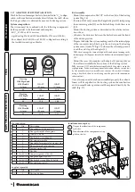
e dimensions of the shafts must ensure a minimum gap be-

tween the outer wall of the smoke duct and the inner wall of the 

shaft: 30 mm for circular section shafts and 20 mm in the event 

of a square section shaft (Fig. 24).

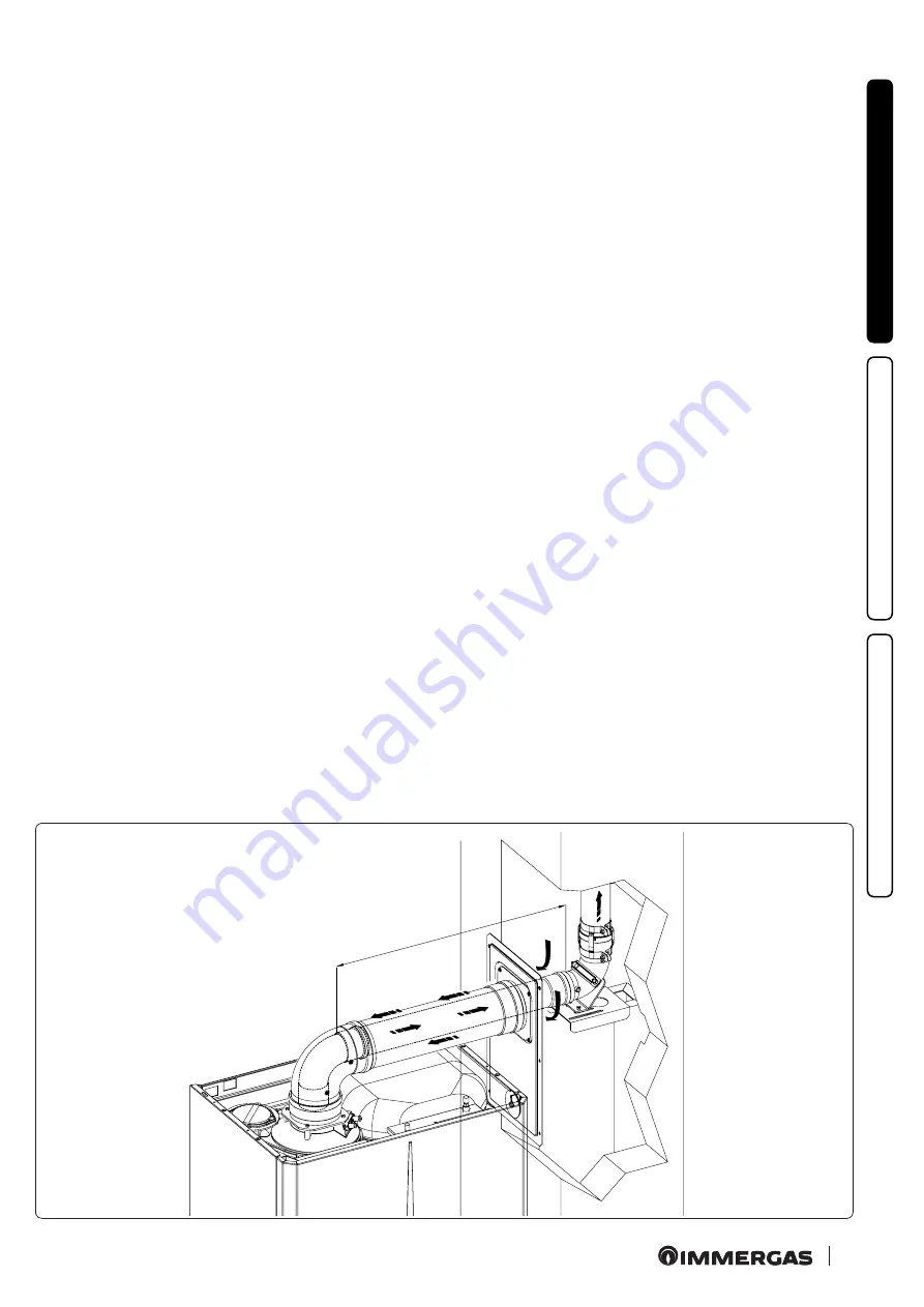
- Maximum 2 changes of direction are allowed on the vertical 

section of the 

fl

ue system with a maximum clearance angle of 

30° with respect to the vertical.

Th

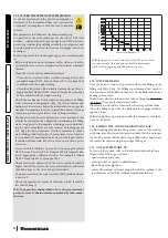
e maximum vertical extension using a 

Ø

 60 ducting system is 

13 m, the maximum extension includes 1 bend 

Ø

 60/10 at 90°, 

1 m of horizontal pipe 60/100, 1 90° ducted bend 

Ø

 60 and the 

roof terminal for ducting.

  To determine the C

93 

fl

ue system in configurations other than 

that described (Fig. 26) one must consider that 1 metre of ducted 

pipe according to the indications described has a resistance factor 

equal to 4.9.

Th

e maximum vertical extension using a 

Ø

 80 ducting system 

is 28 m, the maximum extension includes 1 adapter 60/100 to 

80/125, 1 87° bend 

Ø

 80/125, 1 m of horizontal pipe 80/125, 1 

90° ducted bend 

Ø

 80 and the roof terminal for ducting.

  To determine the C

93 

fl

ue system in configurations other than 

that described (Fig. 26) one must consider the following head 

losses:

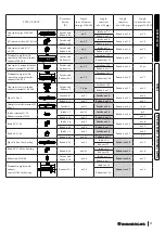
  - 1 m of concentric pipe 

Ø

 80/125 

=

 1 m of ducted pipe;

  - 1 87° bend 

=

 1.4 m of ducted pipe;

  Consequently one must subtract the equivalent length of the 

part added to the 28 m available.

Summary of Contents for Victrix Zeus 25

Page 1: ...VICTRIX ZEUS 25 Instructions and recommendations Installer User Maintenance technician IE 1 042022ENG...

Page 2: ......

Page 3: ...pliance with Regulation 811 2013 61 4 7 Parameters for filling in the package fiche 62 Dear Customer 3 General recommendations 3 Safety symbols used 5 Personal protective equipment 5 1 Boiler installa...

Page 4: ...t be stored in a dry place protected from the weather Damaged products must not be installed Maintenance must be carried out by skilled technical staff For example the Authorised Immergas Service Cent...

Page 5: ...l connection point SHARP SURFACES The symbol indicates the appliance s components or parts that can cause cuts if touched HOT SURFACES The symbol indicates the appliance s very hot components that can...

Page 6: ...ns including scheduled periodic rou tine and special maintenance removal to outdoors in the place for loading and transporting the appliances and components as well as the eventual replace ment of tho...

Page 7: ...and in poten tially dangerous places It is just as important that the intake grids and exhaust terminals are not obstructed It is recommended to check that no flue gas recircula tion is found in the...

Page 8: ...ting of the boiler flue gas may come out the condensate drain after a few minutes operation check that this no longer occurs This means that the trap is filled with condensate to the correct level pre...

Page 9: ...M 1 2 1 2 1 2 3 4 3 4 Key V Electrical connection G Gas supply SC Condensate drain minimum internal diameter 13 mm R System return M System flow RC Domestic hot water pump optional AC Domestic hot wat...

Page 10: ...e and possible disposal follow the supplier s instructions Protect the domestic hot water circuit against freezing by using an accessory that is supplied on request antifreeze kit com prising two elec...

Page 11: ...to per form the hydraulic and gas system connections of the appliance comes as a standard supply Perform the connections respecting the layout of Fig 4 based on the type of installation to be made 1...

Page 12: ...densate can be correctly removed After first ignition check that the drain trap is filled with condensate Para 1 24 Also comply with national and local regulations on discharging waste waters In the e...

Page 13: ...prepared for the application of room chrono thermostats or remote controls which are available as optional kits Fig 7 All Immergas chrono thermostats are connected with 2 wires only Carefully read the...

Page 14: ...correlation between system flow tem perature and external temperature is determined by the position of the central heating selector switch on the boiler control panel or on the CARV2 control panel if...

Page 15: ...installation of air intake terminals and flue exhaust which are fundamental for boiler operation ATTENTION the boiler must be installed exclusive ly with an original Immergas Green Range inspectionab...

Page 16: ...3 0 1 4 Concentric bend 45 80 125 2 1 1 Terminal complete with concentric horizontal intake exhaust 80 125 2 8 1 3 Terminal complete with concentric vertical intake exhaust 80 125 3 6 1 7 90 concentri...

Page 17: ...16 3 m 2 5 Intake m 18 7 Exhaust m 4 9 m 7 7 Exhaust m 13 6 Concentric vertical intake exhaust terminal 60 100 Intake and Exhaust 9 1 4 m Intake m 10 3 Exhaust m 2 7 m 4 3 Exhaust m 7 5 Pipe 80 m 1 I...

Page 18: ...ance is installed in a place where the am bient temperature drops below 0 C use the optional antifreeze kit checking the ambient operating tem perature range shown in the technical data table in this...

Page 19: ...e cover kit includes N 1 Thermoformed cover N 1 Gasket clamping plate N 1 Gasket N 1 Gasket tightening clip N 1 Intake hole covering plate The terminal kit includes N 1 Gasket N 1 Exhaust flange 80 N...

Page 20: ...end 4 with lip seals up to the end stop making sure that the internal 6 and external wall sealing plate 7 have been fitted this will ensure sealing and joining of the elements making up the kit 1 14 C...

Page 21: ...eas where very cold tem peratures can be reached a special anti freeze kit is available that can be installed as an alternative to the standard kit Extensions for vertical kit 60 100 Fig 19 The kit wi...

Page 22: ...t or left hand side of the central exhaust pipe S Both ducts can be routed in any direction Kit assembly Fig 22 install flange 4 on the central hole of the boiler positioning gasket 1 with the circula...

Page 23: ...kit 80 80 The maximum vertical straight length without bends that can be used for 80 intake and exhaust pipes is 41 metres re gardless from whether they are used for intake or exhaust The maximum hori...

Page 24: ...stem curve Quota X Fig 27 whereas the external pipe must reach the end stop of the adapter 1 N B to encourage the removal of possible condensate forming in the exhaust pipe tilt the pipes towards the...

Page 25: ...100 1 90 ducted bend 60 and the roof terminal for ducting To determine the C93 flue system in configurations other than that described Fig 26 one must consider that 1 metre of ducted pipeaccordingtoth...

Page 26: ...by inserting one or more relevant pipes one achieves a system for the evacua tion of the combustion products of a gas appliance consist ing in the combination of an existing or new ducting pipe with...

Page 27: ...gulationsinforce Themultiplefluesandthecombined flues must also only be connected to type C appliances of the same type condensation havingnominalheatinputsthatdonotdifferby morethan30 lesswithrespect...

Page 28: ...er minerals to reduce water filling conductivity up to 10 microsiemens cm Given its low conductivity desalinated water does not only prevent the formation of lime scale but also serves as protection a...

Page 29: ...haust terminals are not obstructed and that they are installed properly check that the drain trap is full and that it prevents any passage of flue gas into the room checkthattherearenoexternalfactorst...

Page 30: ...ead screwdriver Turning clockwise opens the bypass and anticlockwise closes it 1 27 CIRCULATION PUMP During central heating mode the Auto and Fixed operating modes are available Auto A5 0 automatic ci...

Page 31: ...with or without inspectionable filter on request The boiler is designed for installation of system interception cocks to be placed on flow and return pipes of the connection assembly This kit is very...

Page 32: ...9 Storage tank draining fitting 11 Air gas manifold 12 Flue probe 13 Flue gas sample points air A flue gas F 14 Domestic hot water expansion vessel 15 System expansion vessel 16 Condensation module 17...

Page 33: ...nce as a supporting surface ATTENTION Neverexposethewall mountedboiler to direct vapours from a cooking sur face The device can be used by children at least 8 years old as well as by persons with redu...

Page 34: ...iance switch it off disconnect the power close the main gas cock open the windows and call an authorised company e g AuthorisedAfter SalesService ATTENTION if you smell gas in the building close the g...

Page 35: ...function ing active Key 1 Domestic hot water temperature selector 2 Reset Button 3 Summer Winter Button 4 Central heating temperature selector 5 Information buttons 6 Off Stand by On Button 7 Boiler m...

Page 36: ...ia the selector 1 the heating temperature is regulated via selector 4 and the relative tem perature is shown on the display via the indicator 14 From this moment the boiler functions automatically Wit...

Page 37: ...that the boiler is configured correctly 1 16 Fan anomaly This occurs if the fan has a mechanical or electrical fault Press the Reset button 1 20 Parasite flame block This occurs in the event of a lea...

Page 38: ...t 1 73 High flow probe and safety flow probe devia tion detected The board detects an anomaly in the temperature readings of the NTC flow probes the causes may be faulty probe incorrect position poor...

Page 39: ...ustion signal discontinuous The system detects a discontinuous combustion signal The boiler keeps working 1 2 96 Clogged flue This occurs in the event an obstruction is detected in the flue system The...

Page 40: ...regulation EN 1717 2 10 DRAINING THE DOMESTIC HOT WATER CIRCUIT To do this always close the domestic cold water inlet upstream of the appliance Open any domestic hot water tap to discharge the pressur...

Page 41: ...he storage tank use the special draining valve Fig 34 N B before performing this operation close the boil er cold water inlet valve and open any DHW system hot water valve in order to let air into the...

Page 42: ...tion room where provided Even if just one single safety check provides a negative result do not commission the system If additional documentation needs to be consulted for extraordinary maintenance co...

Page 43: ...nd that it is properly fixed to the combustion chamber lid otherwise it must be replaced Visually check that the water safety drain valve is not blocked Check that after discharging the system pressur...

Page 44: ...et non return valve 29 Storage tank draining valve 30 System filling cock 31 Bypass 12 Flue sample point 13 Air sample point 14 Burner 15 Air gas manifold 16 Flow probes 17 Air intake pipe 18 Air vent...

Page 45: ...tank probe B4 External probe optional B5 Return probe B24 Safety flow probe B27 Double flue probe sensor CAR V2 Comando Amico Remoto V2 remote control optional E3 Ignition and detection electrode M1 B...

Page 46: ...manual vent valve Poor production of D H W If a drop in performance is detected during supply of D H W it is possible that the condensation module or D H W heat exchanger is clogged In this case cont...

Page 47: ...ker regarding the modified gas content onto the data nameplate in the con nection box These adjustments must be made with reference to the type of gas used following that given in the table Par 4 1 3...

Page 48: ...fter the flame presence frame flashes or switch to the next heat output parameter by pressing the button 39 3 10 CALIBRATION TYPE INVOLVING THE REPLACEMENT OF A COMPONENT When performing extraordinary...

Page 49: ...operating heat output The calibration stages nominal intermediate and minimum pro gressautomaticallyandyoumustwaituntilcalibrationiscomplete Minimum heat output after having calibrated the boiler with...

Page 50: ...unction must be activated Par 3 11 3 14 FLUE TEST To define the value to set in the flue length F0 parameter detect the parameters during the flue test N B before performing the test ensure that the c...

Page 51: ...max Defines the maximum heat output percentage of the boiler during the centralheatingmodecomparedtothemaximumheatoutputavailable 0 99 80 P3 Relay 1 optional The boiler is set up for functioning with...

Page 52: ...et point maxi mum temperature Defines the maximum flow temperature t0 5 85 C 85 t2 D H W thermostat Defines the flow temperature during the storage tank central heating phase 0 Flow temperature Set DH...

Page 53: ...w electric power supply 0 the automatic vent is enabled only at the first electric power supply after having set the parameter to 0 once the func tion has ended or is interrupted by pressing the butto...

Page 54: ...to variable output for 15 minutes In this state all adjustments are excluded and only the safety thermostat and the limit thermostat remain active To activate the chimneysweepfunction pressthe buttonu...

Page 55: ...f from the bracket h by pushing upwards and towards you 3 22 CASING REMOVAL To facilitate boiler maintenance the casing can be completely removed as follows Lower grid Fig 48 1 Loosen the two screws...

Page 56: ...ENANCE TECHNICIAN Ref X Sides Fig 52 12 Unscrew the side k fastening screws l 13 Remove the sides by extracting them from their rear seat Ref X Control panel Fig 51 9 Loosen the fixing screws i from t...

Page 57: ...air combustion temperature C 50 50 Intake exhaust available head F0 0 Pa 68 68 Intake exhaust available head F0 1 Pa 103 103 Intake exhaust available head F0 2 Pa 138 138 4 2 COMBUSTION PARAMETERS MET...

Page 58: ...ating temperature max operating field C 25 85 Central heating System expansion vessel total volume l 5 8 Central heating expansion tank pre charge bar MPa 1 0 0 1 Total volume domestic hot water expan...

Page 59: ...eat input Qn min Central heating minimum heat input Qnw max DHW maximum heat input Qn max Central heating maximum heat input Pn min Minimum heat output Pn max Maximum heat output PMS Maximum system pr...

Page 60: ...t nominal heat output in high tem perature mode 4 87 0 At 30 of nominal heat output in a low temperature mode P1 6 6 kW At 30 of nominal heat output in a low temperature mode 1 95 7 Auxiliary electric...

Page 61: ...for the maintenance technician and adhere to the frequencies and methods set out herein Parameter value Annual energy consumption for the central heating mode QHE 37 GJ Annual electricity consumption...

Page 62: ...ler 1 Temperature control From temperature control board Supplementary boiler From boiler board Supplementary heat pump From the heat pump board Solar contribution and supplementary heat pump Select t...

Page 63: ...iency of the set of products indicated in this sheet may not reflect the actual energy efficiency after installation since such efficiency is affected by additional factors such as the heat loss in th...

Page 64: ...ated load profile Solar contribution From the board of the solar device 1 I 2 1 1 x I 10 x II III I Auxiliary electricity 3 G F E D C B A A A A 27 27 27 28 27 27 27 28 30 30 30 32 33 34 35 36 36 37 38...

Page 65: ...rgy efficiency class in colder and hotter climate conditions Colder 0 2 x Hotter 0 4 x Stated load profile Solar contribution From the board of the solar device 1 _____ 2 1 1 x _____ 10 x _____ ____ _...

Page 66: ...66 66...

Page 67: ...67 67...

Page 68: ...mmergas S p A 42041 Brescello RE Italy Tel 0522 689011 Fax 0522 680617 Certified company ISO 9001 This instruction booklet is made of ecological paper Cod 1 042022ENG rev ST 003654 001 02 19 Inglese p...

Reviews: