HD1-E CANopen instruction manual
- 16 -
⚫
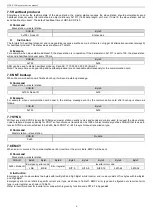
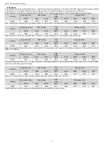
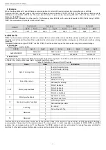
Example
For example, when slave station address=3, set the function code of HD1 inverter P15.13=1.
Command: The parameter address of P15.02 is 0x0F02. According to the protocol, the request code, parameter address and request
data of PDO1 Rx are seperately 0x02, 0x0F0D and 0x01, so PDO1 Rx sent by master station is shown as follows.
COB-ID
Request code
Parameter address
Request data
Byte0
Byte1
Byte2
Byte3
Byte4
Byte5
0x203
0x02
0x00
0x02
0x0F
0x01
0x00
If the inverter parameters are modified successfully, PDO1 Tx in response is as follows.
COB-ID
Response code
Error code
Response data
-
Byte0
Byte1
Byte2
Byte3
Byte4
Byte5
Byte6
Byte7
0x183
0x01
0x00
0x00
0x00
0x01
0x00
0x00
0x00
8.3 PDO2 Rx
PDO2 Rx is used to modify control word and realtime process quantities (set value1, 2 and 3). The control word is for controlling
start-up/stop of the inverter while set values are for controlling realtime running values such as set frequency.
⚫
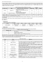
Command
Master station
→slave station
COB-ID
Byte0
Byte1
Byte2
Byte3
Byte4
Byte5
Byte6
Byte7
0x300+NODEID
Control word
Set value1
Set value2
Set value3
0x2101.00
0x2100.03
0x2100.04
0x2100.05
⚫
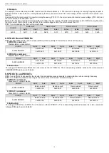
Instruction
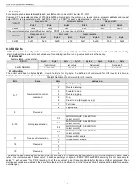
The control word has two bytes, Byte0 for low byte, Byte1 for high byte. The definition of control word for HD1 inverter is shown in
Table22. As other models, please refer to related inverter manuals.
Table22 Definition of control word for HD1 inverter
Bit
Name
Value
Instruction
0~7
Communication control
command
1
Forward running
2
Reverse running
3
Forward jogging
4
Reverse jogging
5
Stop
6
Coast to stop
(Emergency stop)
7
Fault reset
8
Jogging stop
8
Reserved
9~10
Motor group selection
00
MOTOR GROUP 1 SELECTION
(select motor1)
01
MOTOR GROUP 2 SELECTION
(select motor2)
02
MOTOR GROUP 3 SELECTION
(select motor3)
03
MOTOR GROUP 4 SELECTION
(select motor4)
11
Torque control selection
1
Torque control
enable
0
Torque control
disable
14
Reserved
1
0
15
Reserved
1
0
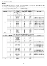
The function of each set value can be set by the function codes in the same way as PZD receiving of CANOPEN communication. Please
refer to the inverter manual. The set value1, 2 and 3 seperately correspond to PZD2, PZD3 and PZD4 receiving. It is only necessary to
select
“1: set frequency” for PZD2 receiving to set the set value1 to set frequency, similarly for functions of other set values. When
multiple set values are enabled at the same time, there will be no influence on other values setting if a value setting fails (for example,
out of range).

