HD1-E CANopen instruction manual
- 17 -
⚫
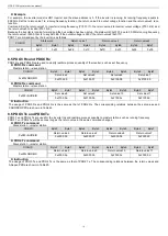
Example
When the slave address=3, adopt CANopen communication to control HD1 inverter and set the running frequency at 50Hz.
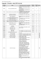
Command: At first, set start mode of the inverter to CANopen communication (P00.01=2, P00.02=1) and frequency reference way to
CANopen communication (P00.06=9). Then use the set value2 to give running frequency (P15.03=1, that is to say, select
“1: set
frequency
” for PZD3.)
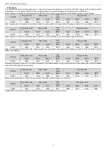
Control word=0x01 indicates to run the inverter. The frequency is set to 50Hz, so the set value2 equals to 5000, that is to say, 0x1388.
PDO1 Rx command sent by master station is as follows.
COB-ID
Control word
Set value1
Set value2
Set value3
Byte0
Byte1
Byte2
Byte3
Byte4
Byte5
Byte6
Byte7
0x303
0x01
0x00
0x00
0x00
0x88
0x13
0x00
0x00
8.4 PDO2 Tx
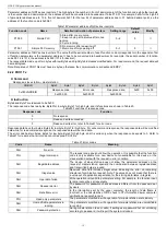
PDO2 Tx, the command sent by the inverter to master station, contains state word and realtime process quantity (set value1, 2 and 3).
The state word is to report the state of the inverter and the return value is to send realtime running values of the inverter, such as running
frequency.
The default transmission type of PDO2 Tx is 254. PDO2 Tx will be sent as long as the state word or any return value changes.
⚫
Command
Slave station
→master station
COB-ID
Byte0
Byte1
Byte2
Byte3
Byte4
Byte5
Byte6
Byte7
0x280+NODEID
State word
Return value1
Return value2
Return value3
0x2001.00
0x2000.03
0x2000.04
0x2000.05
⚫
Instruction
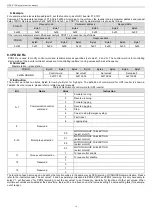
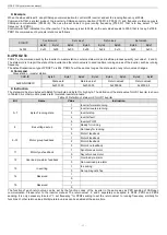
The state word has two bytes with Byte0 for low byte and Byte1 for high byte. The definition of the state value for HD1 inverter is shown
in Table23. As other models, please refer to related inverter manuals.
Table 23 Definition of state word for HD1 inverter
Bit
Name
Value
Instruction
0~7
Byte of running state
1
Inverter forward running
2
Inverter reverse running
3
Inverter stop
4
Inverter fault
5
Inverter POFF
8
Bus voltage set up
1
Ready for running
0
Not ready for running
9~10
Motor group feedback
0
Motor1 feedback
1
Motor2 feedback
2
Motor3 feedback
3
Motor4 no feedback
11
Motor type feedback
1
Synchronous motor
0
Asynchronous motor
12
Overload pre-alarm feedback
1
Overload pre-alarm
0
Non-overload pre-alarm
13
In exciting
1
In exciting
0
Set up magnetic flux
14
Reserved
1
0
15
Reserved
1
0
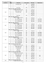
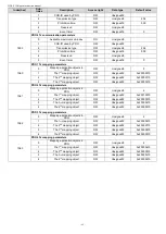
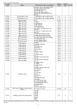
The function of each return value can be set by the function codes of the inverter in the same way as PZD sending of CANopen
communication. Please refer to the inverter manual. The return value1, 2 and 3 seperately correspond to PZD2, PZD3 and PZD4
sending. It is only necessary to select
“1: set frequency” for PZD2 sending to set the return value1 to running frequency, similarly for
functions of other return values. Multiple return values can be enabled at the same time.


