HD1-E CANopen instruction manual
- 26 -
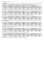
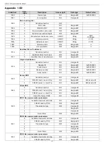
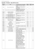
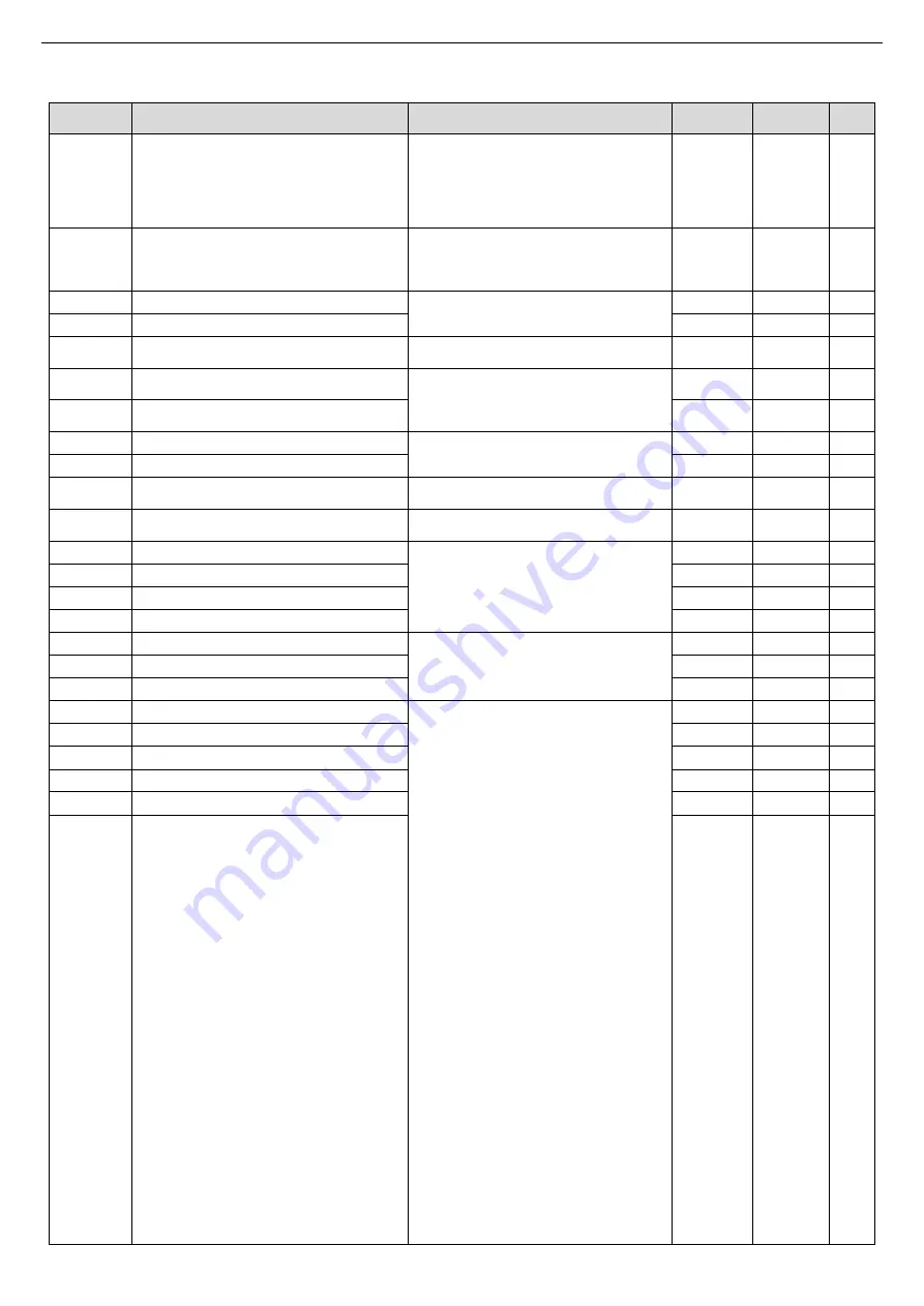
Appendix 2 Function codes (HD1 inverter)
Function
code
Name
Detailed instruction of parameters
Setting
range
Default
value
Modify
P00.01
Running command channel
0: Keypad running command channel
(LED off)
1: Terminal running command channel
(LED flickering)
2: Communication running command
channel (LED on)
0~2
0
○
P00.02
Communication running command channel
0: MODBUS communication channel
1: CANOPEN communication channel
2: Ethernet communication channel
3: CAN communication channel
0~3
0
○
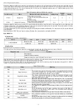
P00.06
A frequency command
9: CANOPEN communication setting
0~12
0
○
P00.07
B frequency command
0~12
1
○
P03.11
Torque setting way
8: CANOPEN communication setting
torque
0~10
0
○
P03.14
Forward upper limit frequency setting
source of torque control
7: CANOPEN communication setting
upper limit frequency
0~9
0
○
P03.15
Reverse upper limit frequency setting
source of torque control
0~9
0
○
P03.18
Electric torque upper limit setting source 6: CANOPEN communication setting
torque upper limit
0~8
0
○
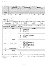
P03.19
Braking torque upper limit setting source
0~8
0
○
P04.27
Voltage setting channel
8: CANOPEN communication setting
voltage
0~10
0
○
P05.12
Virtual terminal setting
2: CANOPEN communication
virtual
terminals are valid.
0~4
0
◎
P06.01
Y output
24: CANOPEN communication
virtual
terminal output
0~40
0
○
P06.02
HDO output
0~40
0
○
P06.03
Relay RO1 output
0~40
1
○
P06.04
Relay RO2 output
0~40
5
○
P06.14
AO1 output
16: CANOPEN communication set value1
17: CANOPEN communication set value2
0~30
0
○
P06.15
AO2 output
0~30
0
○
P06.16
HDO high speed pulse output
0~30
0
○
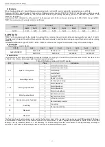
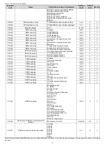
P07.27
Current fault type
0: No fault
1: Inverter unit U-phase protection (out1)
2: Inverter unit V-phase protection (out2)
3: Inverter unit W-phase protection (out3)
4: ACC overcurrent (OC1)
5: DEC overcurrent (OC2)
6: Constant speed overcurrent (OC3)
7: ACC overvoltage (OV1)
8: DEC overvoltage (OV2)
9: Constant speed overvoltage (OV3)
10: Bus undervoltage (UV)
11: Motor overload (OL1)
12: Inverter overload (OL2)
13: Phase loss of input side (SPI)
14: Phase loss of output side (SPO)
15: Rectifier module overheat (OH1)
16: Inverter module overheat (OH2)
17: External fault (EF)
18: 485 communication error (CE)
19: Current detection fault (ItE)
20: Motor autotuning error(tE)
21: EEPROM operation failure (EEP)
22: PID feedback offline (PIDE)
23: Braking unit fault (bCE)
24: Running time arrival (END)
25: Electronic overload (OL3)
26: Panel communication error (PCE)
27: Upload parameter error (UPE)
28: Download parameter error (DNE)
29: CANOPEN communication error
(E-DP)
30: Ethernet communication error
(E-NET)
31: CAN communication error (E-CAN)
32: Short circuit to earth fault1 (ETH1)
●
P07.28
Last one fault type
●
P07.29
Last two fault types
●
P07.30
Last three fault types
●
P07.31
Last four fault types
●
P07.32
Last five fault types
●


