HD1-E CANopen instruction manual
- 3 -
4. Parts introduction
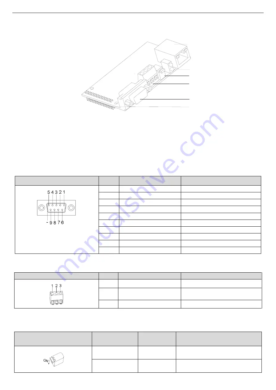
See the parts of CANopen communication card in Fig1.
A
B
C
D
E
F
EC-T
X10
5
Fig1 Parts of CANopen communication card
A
–CANopen communication port (DB9 female)
B
–CANopen communication port terminal (3pin)
C
–CANopen terminating resistor switch
D
–CANopen status indicator light
F
–communication card port pin
Note: Two address knobs will not be installed, and the communication address is set by inverter function code.
Users can select either of two CANopen communication ports, DB9 female (A) and 3pin open terminal (B).
See the functions of DB9 female communication port in Table 4.
Table 4 Functions of CANopen DB9 female communication port
CANopen communication port (DB9
female)
Pin
Function
Description
1
-
2
CAN_L
CANopen bus low level signal
3
-
4
-
5
CAN_SHLD
CANopen bus shielding
6
-
7
CAN_H
CANopen bus high level signal
8
-
9
-
-
CAN_SHLD
CANopen bus shielding
See the functions of 3pin open terminal communication port in Table 5.
Table 5 Functions of 3pin open terminal communication port
3pin open terminal
Pin
Function
Description
1
CAN_L
CANopen bus low level signal
2
CAN_SHLD
CANopen bus shielding
3
CAN_H
CANopen bus high level signal
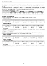
See the functions of terminating resistor switch in Table 6.
Table 6 Functions of terminating resistor switch
Terminating resistor switch
Direction
Function
Description
Up
OFF
No terminating resistor connected with
CAN_H and CAN_L
Down
ON
120
Ω terminating resistor connected with
CAN_H and CAN_L


