Slew Drives
Installation and commissioning
31
2.
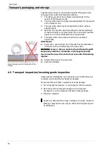
Arrange the hardness gap (
section 5.3.1 "Hardness gap") of
the bearing ring charged with point load so that it is offset by
90° relative to the main load-carrying zone. The main load-
carrying zone is in the main slewing range.
CAUTION!
CAUTION!
CAUTION!
CAUTION!
The hardness gap or the filling plug in a slewing
ring constitute a zone of decreased load-carrying capacity.
The service-life of the slew drive will be reduced
significantly, if the hardness gap is in the main slewing
range. Fracture of bearing ring for example may cause
slew drive failure. Consequently place this marked point in
a reduced load zone if possible.
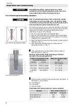
Fig. 21: Check the support surface
3.
Use a feeler gauge to check whether the support surface of the
slew drive is completely supported by the mounting structure. If
this is not the case, the support surface of the mounting
structure must be reworked (
section 5.2.3 "Determining
flatness deviation, and perpendicularity deviation and
deformation").
5.3.3
Bolting the slew drive
WARNI
WARNI
WARNI
WARNING
NG
NG
NG
Do not use impact screwdrivers. Using an impact
screwdriver may cause impermissible deviations between
the bolt tightening forces. Failure of the bolted union with
the mounting structure may cause severe personal injury
or material damage.
Mount the slew drive in unstressed state.
Strictly comply with the procedure specified below to avoid
impermissible deviations between the bolt tightening forces:
First fasten the housing, then fasten the toothed bearing ring!
1.
Lightly oil the bolt thread (not when using bolt locking devices
with adhesive).
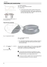
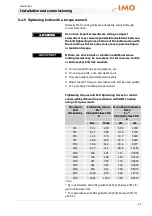
Fig. 22: Tighten crosswise
2.
Pretension the bolts, with washers if required, crosswise in 3
steps, 30%, 80%, and 100% of the tightening torque, or the
hydraulically applied pretension force.
3.
In this process turn the unscrewed ring several times. Repeat
the procedure for the bearing ring that has not yet been bolted.
If using a hydraulic bolt-tensioning cylinder the tensioning forces
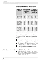
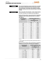
for the bolt pretension should not exceed 90% of yield strength
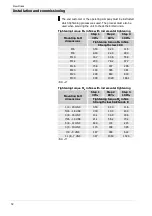
(
Tab. 10 and 11).


