Slew Drives
Installation and commissioning
33
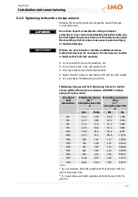
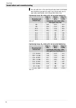
Tightening torque M
A
in ft-lbs with incremental tightening
Step 1
30%
Step 2
80%
Step 3
100%
Mounting bolt
dimensions
Tightening torque M
A
in ft-lbs
Strength class 10.9
M6
2.50
6.80
8.50
M8
6.20
16.5
20.7
M10
12.3
33.0
41.2
M12
21.6
57.6
72.0
M16
54.3
145
181
M20
107
284
355
M24
184
490
612
M30
368
980
1225
Tab. 14
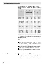
Tightening torque M
A
in ft-lbs with incremental tightening
Step 1
30%
Step 2
80%
Step 3
100%
Mounting bolt
dimensions
Tightening torque M
A
in ft-lbs
Strength class SAE Grade 8
1/4 - 20 UNC
2.60
6.90
8.60
5/16 - 18 UNC
5.40
14.4
18.0
3/8 - 16 UNC
9.70
25.8
32.3
7/16 - 14 UNC
15.6
41.6
52.0
5/8 - 11 UNC
47.7
127
159
3/4 - 10 UNC
85.5
228
285
7/8 - 9 UNC
138
369
461
1 1/8 - 7 UNC
294
785
981
Tab. 15
5.3.4
Determining the tilting clearance
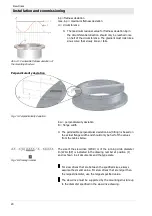
Tilting clearance increases as raceway system wear increases. To
determine the increase in tilting clearance a basic measurement
must be executed in installed status and prior to first-time
operation. This is the only way to determine changes.
Fig. 23: Determine tilting clearance
1
Upper mounting structure
2
Tilting direction
3
Main load-carrying zone
4
Lower mounting structure

