Slew Drives
Maintenance
40
Checking the tilting clearance increase
d
k
directly on the
slew drive
The measured value m1 determined at installation serves as the
base value (
section 5.3.4 "Determination of tilting clearance").
Determine the value mx as described in the section 5.3.4
"Determining the tilting clearance".
Subtract the base value m1 from the value mx determined in
the inspection measurement:
Checking the tilting clearance increase
d
k
but not directly
on the slew drive
Proportionally convert the tilting clearance increase each time a
measurement is taken (after the installation measurement ) and
compare with
d
k
perm.
6.4.3
Checking the circumferential backlash
CA
CA
CA
CAUTION
UTION
UTION
UTION
Toothing wear causes increased circumferential backlash.
When the maximum permissible circumferential backlash
is reached, then the system must be brought to a standstill
and the slew drive must be replaced immediately, as safe
operation can no longer be ensured.
1.
Determine the circumferential backlash in accordance with
5.3.5 "Determining the circumferential backlash".
2.
Compare the determined value with the permissible values of
the table.
See the type plate for the module specification.
For a module that is between the specified values, use the
value for the smaller module.
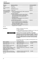
Circumferential backlash angle limit values
Module of
the
toothing
Limit of
circumferential
backlash angle
Module of
the
toothing
Limit of
circumferential
backlash angle
3
34°
6
28°
4
32°
6/2
convolution
14°
4/2
convolution
16°
7
28°
4,5
31°
7/2
convolution
14°
5
30°
8
27°
5/2
convolution
15°
8/2
convolution
13.5°
Tab. 18
d
k
= mx – m1 ≤
d
k
perm
d
k
perm = 0.45 mm
d
k
perm = 0.0177 in

