Slew Drives
Structure and function
5
1
Structure and function
1.1
Brief description
Slew drives are used for concurrent transmission of axial and radial
forces, as well as transmission of tilting moments. Slew drives
consist of a ball or roller slewing ring, hydraulic or electric drives,
and a completely enclosing housing. Force is transmitted to the
mounting structure through bolts. For this purpose through holes
or threads are provided in the inner and outer ring.
1.2
Overview
Series WD slew drives are designed with worm gear. Series SP
slew drives are designed with spur gear and straight toothing.
1.2.1
WD-L series (light series)
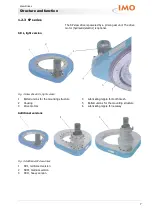
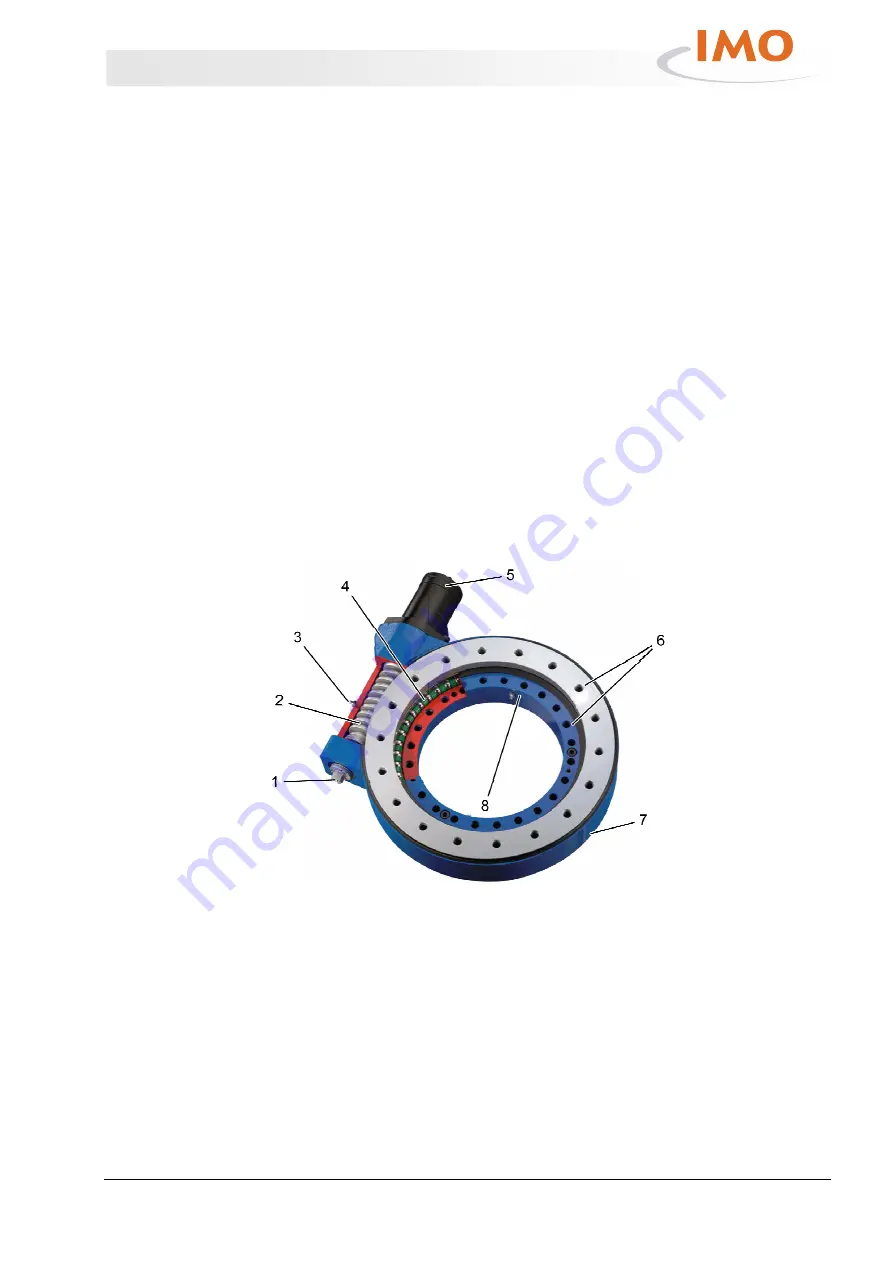
The lighter series is designated as the WD-L series. The drive
motor (hydraulic/electric) is optional. Additional optional
components are potentiometers, permanent brake or front-end
brake.
Fig. 1: Slew drive WD-L
1
Connection for options: Potentiometer,
permanent brake or front-end brake
2
Worm shaft
3
Lubricating nipple
4
Ball slewing ring
5
Option: Drive motor
6
Bolted unions for the mounting structure
7
Housing
8
Lubricating nipple


