background image


COMTEST    User Guide 

 11 

Version. 3.1  November 2003 


IMPACT      


Scotland, United Kingdom 


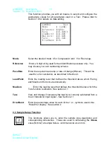
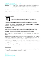
After  all  internal  checks  are  completed,  the  first  screen  you  see  is  referred  to  in  this 
manual  as  the  Main-Screen  (above  right).    This  is  the  display  from  where  you  will 
monitor the development of a test, and where you will see its results:  
 
For configuration of all the parameter displayed in this  screen, select the 

TEST

 function 

- See Section 2.2 
 
The 

PaceRate

  shown  (KN/  sec)  is  the  last  one  configured.    It  refers  to  the  rate  of 

change in manual loading required from a test.  
 
Whilst  the  current  load  reading  is  below  a 

LoadPoint

  level  and  is  in  IDLE  mode,  the 

display  will  update  as  the  load  changes.    At  this  point,  you  can  choose  any  of  the 
instrument functions described in the next sections.  
 
Furthermore, if the load is below a 

MaxZero

 threshold, you can select the function as 

described in Section 2.1 
 
As  soon  as  the  load  increases  above  the 

LoadPoint

  level and is in “RUN” mode, the 

actual test is assumed to have started, and all other functions are disabled until the test 
is finished. 
 
In  compression  mode  the  load  is displayed from 000.0 to 399.9 t hen 400  to 3000 kN 
and in Flexural mode the load is displayed from 000.00 to 100.00 Kn.  
 
When  the  test  runs,  internally  the  instrument  generates  a  target  ramp  using  the 
configured 

PacePate.

    Five  times  a  second,  the  current  loading  is  compared  against 

this  target  ramp,  and  any  differences  between  them  - 

PaceError

  -  are  continuously 

updated. 
 
 
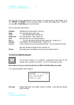
The PaceError is displayed on the bottom LCD row as follows:  
 

As a bar-graph.  This has its starting point, represented by >0< fixed on an LCD 
co-ordinate. 

  Negative errors are represented by a bar |||||||||0  growing leftwards 

  Positive errors are represented by a bar           0|||||||||  growing rightwards 


Summary of Contents for CT415

Page 1: ...User Guide User Guide 3000kN Compression Machine CT415 Impact Test Equipment Ltd www impact test co uk www impact test com...

Page 2: ...t Ltd Building 21 Stevenston Ind Est Stevenston Ayrshire KA20 3LR T 01294 602626 F 01294 461168 E sales impact test co uk Test Equipment Web Site www impact test co uk Test Sieves Accessories Web Site...

Page 3: ...C serial port configured as 9600 baud 8 bits 1 stop and no parity for test printout or dumping the results directly to a computer z Memory for configuration and data logging purposes z Storage for up...

Page 4: ...ce Pieces to allow the testing of 100mm and 150mm cubes Optional Accessory Centring jig for positive location of 100 150mm cubes 3000kN Load Frame The upper platen is ball seated whilst the lower plat...

Page 5: ...ne start to load press the RUN button on the Comtest keypad Manipulate the load rate with the control and keep it within the limits shown on the Comtest display known as the pace rate Once the sample...

Page 6: ...1 5 OPTION SELECTION 8 1 6 DATA EDITING 9 1 7 PASSCODE ENTRY 10 2 0 USING COMTEST 10 2 1 TARE FUNCTION 12 2 2 TEST SETUP FUNCTION 12 2 3 SAMPLE SETUP FUNCTION 13 2 4 DISPLAY RESET FUNCTION 15 2 5 REVI...

Page 7: ...o processor based electronics which includes 16 bit multi channel ADC with automatic programmable gains RS232 C serial port configured as 9600 baud 8 bits 1 stop and no parity for test printout or dum...

Page 8: ...ons These are all located at the back of the instrument and are shown in detail in the following diagrams To start COMTEST simply apply power to the instrument by switching it ON The display should sh...

Page 9: ...ed COMPUTER The following pins are used 1 2 Front Panel Display This module provides the means of presenting all the information available from the COMTEST instrument its functions and corresponding p...

Page 10: ...rows are the Active rows and contains the option that can be selected or the data that can be edited e g Load KN Length mm Area mm2 Stress MPa 1 3 Front Panel Keypad All data entry editing and functio...

Page 11: ...1 November 2003 IMPACT Scotland United Kingdom Save Log Test View Select Exit No Change Help Help Tare Function Test Function Sample Definition Clock Set up Display Logged Data Print Logged Data Set u...

Page 12: ...e HELP key again to return to the normal display mode 1 5 Option Selection Many of the COMTEST functions require you to select one of a number of options available e g configuring ranges viewing logs...

Page 13: ...etc In these cases a list of editable fields will be displayed The list may include 1 2 or more items but only up to 3 can be seen at a time In this case it can be scrolled to bring up further option...

Page 14: ...updated in the display 1 7 Passcode Entry Of all the COMTEST functions calibration and configuration are protected by a pass code entry against misuse or unauthorised operation Pass codes are entered...

Page 15: ...Furthermore if the load is below a MaxZero threshold you can select the function as described in Section 2 1 As soon as the load increases above the LoadPoint level and is in RUN mode the actual test...

Page 16: ...t you need to set up not only Test but also Sample characteristics date and time configure and calibrate the ranges etc The rest of this manual shows you how to do this To access a function from the M...

Page 17: ...ter the loading level that defines the threshold above which Pacing and Maximum Hold occur automatically MaxZero Enter the loading level that defines the threshold below which the Tare function is all...

Page 18: ...to enter the appropriate dimensions Standard Cube Choose one of the available dimensions See Section 1 5 Standard Cylinder Choose one of the available diameter sizes See Section 1 5 COMTEST Sample Sta...

Page 19: ...et Function This function achieves 2 objectives It stores current test set up and results information into a special log space in non volatile memory This allows COMTEST to remember previous test resu...

Page 20: ...t want to save the results Press ENTER SELECT if you do want to log the results Please refer to Section 2 5 for details on logged data While this is being logged you will see a display for a few secon...

Page 21: ...ace the rate used when the test was carried out Section 2 2 Sample a description of the selected type Section 2 3 X Area cross sectional area of the selected sample This is obtained from the type and...

Page 22: ...ins date and time from the moment you set it If for any reason you need to change this enter new values as described in Section 1 6 Simply enter the time and or date as above then press the Enter Key...

Page 23: ...you use return a calibrated Full Scale signal COMTEST assumes the calibrated 0 divisions correspond to ZERO signal Please refer to Section 2 1 Tare for additional facilities available to compensate f...

Page 24: ...0 to 100 00 KN fo r the Flex range Press ABORT to return to the main display 2 9 Channel Calibration This function requires pass code access See Section 1 7 If entered correctly this function allows...

Page 25: ...ate the ZERO set on the transducer Choose this option to re calibrate the transducer to the FSD value set Choose this option to exit the calibration routine In all cases the new calibration data is sa...

Page 26: ...f these parameters 2 12 Running A Test At this point you must already have configured and calibrated all transducer inputs Select test configuration menu press 1 and set all functions as required Pres...

Page 27: ...eed clarification In the diagram shown on page 4 TX is for data coming out of the Comtest and RX for data going in This means that when connecting the Comtest to a computer etc a cross over cable must...

Reviews: