COMTEST User Guide
4
Version. 3.1 November 2003
IMPACT
Scotland, United Kingdom
1,. General Details
This section presents general purpose descriptions of functions and usage of the
COMTEST instrument, necessary to operate correctly.
1. 1 Instrument Connections
.
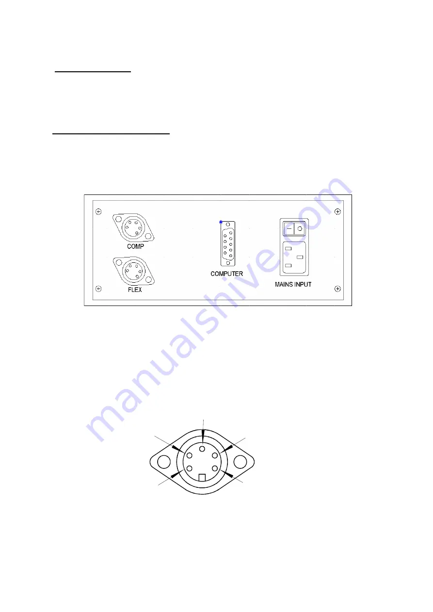
These are all located at the back of the instrument, and are shown in detail in the
following diagrams:
To start COMTEST, simply apply power to the instrument by switching it ON. The
display should show the initial , introductory message as described in Section 2.
Connect the Compression transducer to the socket marked COMP and the FLEXURAL
transducer to the socket marked FLEX. The following pin -out is used for connections:
0V
-5V
+5V
+Ve Input
-Ve Input


