906-0731-04 Rev. B Sept. 2012
Page 24 of 68
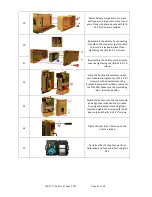
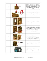
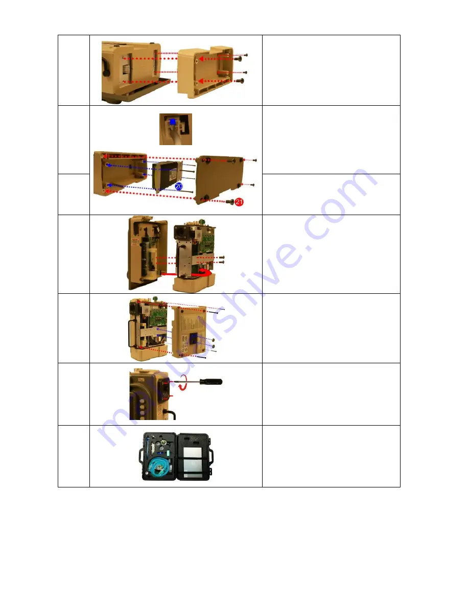
19
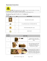
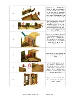
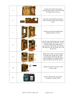
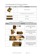
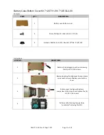
Rotate battery compartment to mate
with upper and lower case cutouts and
press firmly into place. Secure with (4) 6-
32 X 5/16 screws provided.
20
Re-assemble the battery by connecting
its cable to the connector (pull on cable
to insure it is locked in place) then
tightening the (4) 6-32 X 2 ¼ screws.
21
Re-assemble the battery compartment
cover by tightening the (4) 6-32 X 5/16
screws.
22
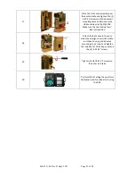
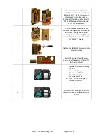
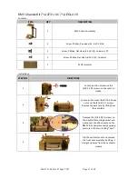
Place the front case assembly over the
vent module and tighten the (2) 4-40 X ¼
screws unto the dovetail mounting
bracket. Reconnect the ribbon cable unto
the PIM PCB. Make sure the two locking
“ears” lock into position.
23
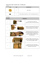
Attach the back case to the vent module
and align cover with handle, air intake
housing and dovetail mounting studs.
Insert and tighten the included (2) 10-32
Keps nuts and the (4) 6-32 X 2” screws.
24
Tighten the (4) 8-32 X 3 screws on the
outer air intake.
25
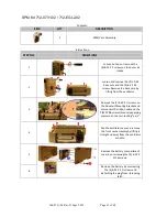
Perform HiPot Testing then perform
Calibration and Functional Test using the
RCS.


