906-0731-04 Rev. B Sept. 2012
Page 41 of 68
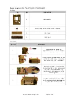
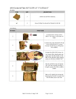
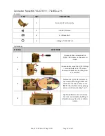
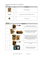
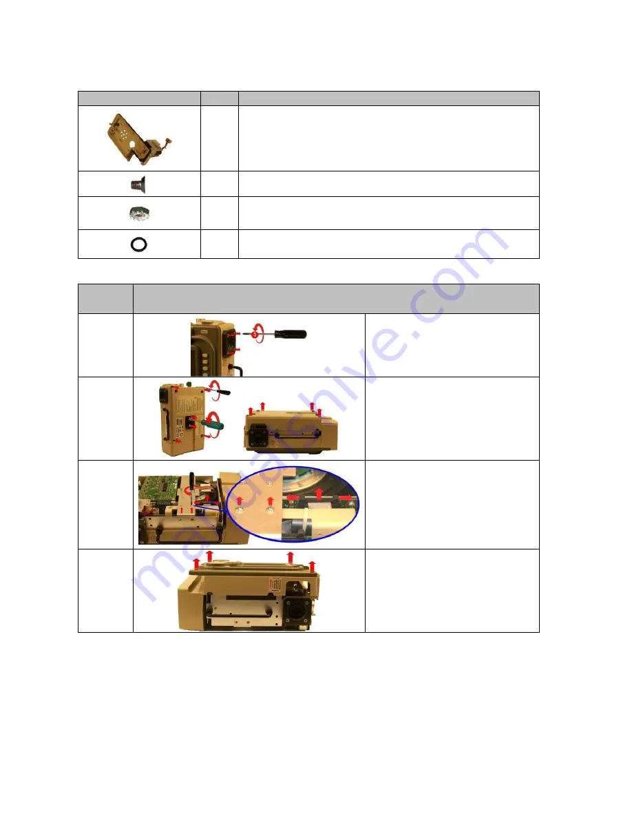
Connector Panel Kit 712-0731-11 / 712-EGL2-11
Contents:
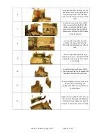
Instructions:
STEP NO.
DIRECTIONS
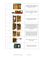
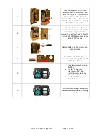
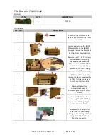
1
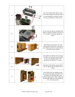
Loosen but do not remove the
(4) 8-32 X 3 screws on the outer air
intake.
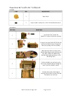
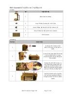
2
Loosen and remove the (2) 10-32 Keps
nuts and the (4) 6-32 X 2 screws.
Remove the back case by lifting from
the ventilator.
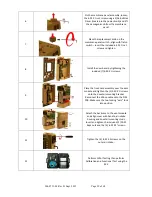
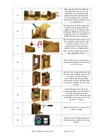
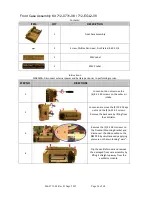
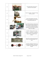
3
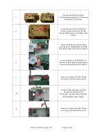
Remove the (2) 4-40 X ¼ screws on
the Dovetail Mounting Bracket and
disconnect the ribbon cable on the
PIM PCB by simultaneously applying
pressure on the two locking “ears”.
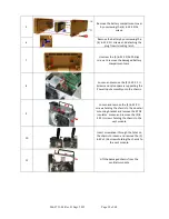
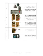
4
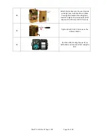
Flip the ventilator over and remove
the front case assembly by lifting it
straight up away from the ventilator
module.
ITEM
QTY
DESCRIPTION
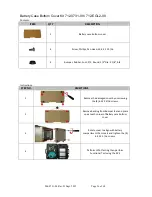
1
Connector Panel Assembly
3
8-32 X 1/4 Screw
4
6-32 Keps Nut
2
O-Ring ½” OD X 3/8” ID

