background image

22

Audio Button

When the LED indicator over the audio button is on, the monolight will emit a 

beep to indicate various alerts and functions. To turn this function off, press the 

audio button once. The LED indicator will turn off. Press the audio button again 

to reactivate the function.

Note:

 When the audio function is disabled, the modeling light will act as a 

recycle indiactor. When the flash is fired, the modeling light will blink off until the 

capacitors have recharged, and then turn on again.

Overheating Protection

After a long shooting session at a high power output, the recycling time of 

the flash will increase automatically until the flash cools to a safe level. Once 

cooled, it will begin operating as usual.

Overvoltage and Overcurrent Protection

The flash is protected against unstable voltages. Overcurrent protection is useful 

when using a power generator (gasoline or electric) to power the flash unit.

Error Codes

In the event of a malfunction, the LED screen will display a blinking error code. 

In addition, error codes E2 and E3 are accompanied by a beep warning.
E1: Temperature transducer problem. Turn the unit off immediately and contact 

Impact customer service.
E2: This error code can appear after a long shooting session at high output or 

rapid sequence. Turn off the flash unit and allow it to rest for 30 minutes.
E3: This error code will appear when the internal voltage of the flash is too high. 

Turn off the power immediately. After 5 minutes, turn the flash back on. If the 

error is still displayed on the LED screen, turn off the monolight and contact 

Impact customer service.

Other Functions and Protective Features

Summary of Contents for VC-500WL2KN

Page 1: ...INSTRUCTIONS VC 500WLN Digital Monolight...

Page 2: ...You can trigger the monolight from a distance of 328 feet 100 m when it s partnered with the VC 500WLXMT transmitter included with kits only sold separately Paired with the unit s integrated group fu...

Page 3: ...led kit case User manual VC 500WL2KN Digital Monolight 2 Reflector 2 8 ft air cushioned light stand 2 40 in umbrella white with black backing 2 24 36 in softbox with speed ring Wireless controller AC...

Page 4: ...in or powering on the unit Never operate the flash with the protective cap on Make sure this product is powered off when plugging it into a power source Turn off the power and unplug the power cord fr...

Page 5: ...5 6 1 4 3 5 Overview Front Side 1 Monolight 2 Mount release 3 Modeling lamp 4 Reflector 5 Flashtube Top 6 Optical sensor 2...

Page 6: ...adjustment dial 7 Test button 8 Audio button 9 Up and down buttons 10 Power indicator 11 Modeling light mode indicators 12 Slave mode button 13 Slave LED indicator 14 Umbrella mount tightening knob 15...

Page 7: ...Only Top 1 Up button 2 Down button 3 Test button 4 Group indicators Right Side 5 Group selector button Left Side 6 Battery compartment Bottom 7 Channel DIP switches 8 Hot shoe mount 9 3 5 mm sync por...

Page 8: ...8 Overview continued Mode 1 Menus Mode 2 Optical slave menu 0 7 Time frame Block time Channel selector 1 16 Group selector A D...

Page 9: ...page 23 The monolight ships with a protective cap Always remove the protective cap before plugging in or powering on the unit To remove the cap push back the mount release and turn the cap counterclo...

Page 10: ...monolights S mount align the accessory with the mount and insert Once inserted rotate the accessory clockwise to secure To remove it from the mount hold down the mount release and rotate the accessory...

Page 11: ...ly with the two and three light kits The VC 500WLXMT remote can be purchased separately The Impact Digital Monolight has an integrated 2 4 GHz 16 channel wireless receiver Using the included transmitt...

Page 12: ...and modeling light settings All of these settings will be active when powering on Important Impact recommends charging the monolight s capacitors for one hour before its initial use and after an exten...

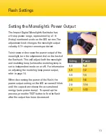
Page 13: ...of the flash unit This will adjust both the monolight and modeling lamp unless the modeling lamp is set to independent mode on or off For information on adjusting the modeling lamp power output refer...

Page 14: ...uitry starts the monolight at a minimum power output then raises it incrementally until the desired power output is reached To activate the modeling lamp press and release the output adjustment dial T...

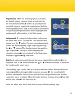
Page 15: ...ns The display shows the modeling light output level Once you have completed this operation the display reverts back to the flash power level after approximately 4 seconds Note Each button press will...

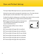
Page 16: ...preflash settings C0 Using your master flash release a test exposure The monolight will automatically memorize the amount of preflashes fired C1 The monolight will flash when it detects another flash...

Page 17: ...ea To set the channel press and hold the slave button for four seconds The c icon appears on the screen to indicate optical slave mode Press the slave button again for the channel selection screen The...

Page 18: ...modeling light using the remote press and hold the button for three seconds Press the or button to adjust the light s output Press and hold the button to turn off the modeling light The modeling light...

Page 19: ...order to wirelessly trigger the flash adjust flash power and turn on off the modeling lamp Groups The Impact Digital Monolight has four groups used to segment remote devices To change the group that t...

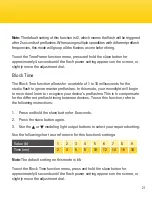
Page 20: ...flash has two settings that enable the flash to ignore a user selected timeframe of preflashes before firing Use these functions when you need to manually control preflash instead of using the Slave...

Page 21: ...er preflashes In this mode your monolight will begin to record and learn to recognize your device s preflashes This is to compensate for the different preflash timing between devices To use this funct...

Page 22: ...Overvoltage and Overcurrent Protection The flash is protected against unstable voltages Overcurrent protection is useful when using a power generator gasoline or electric to power the flash unit Error...

Page 23: ...n glove or soft dry cloth carefully unscrew the modeling light bulb 3 Pick up the replacement bulb with the glove or cloth and insert the base into the modeling light socket Turn it clockwise until ti...

Page 24: ...es or hold a soft dry cloth and use a pair of needle nose pliers to carefully unhook the retention spring loop of the flash tube Make sure it is disengaged from the flash tube 5 Once it is unhooked gr...

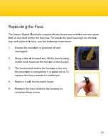
Page 25: ...owing instructions 1 Ensure the monolight is powered off and unplugged 2 Using a slotted screwdriver lift the fuse housing via the nook found on the flat side of the AC jack 3 The fuse located within...

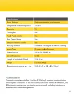
Page 26: ...250 W Max SSC soft start circuitry Modeling Lamp Control Proportional Independent Off Triggering Method 16 channel wireless transmitter included with kits only direct connect 6 35 mm phono plug to PC...

Page 27: ...mbrella mount Power Source 100 to 130 V 50 60 Hz Circuit Protection 12 5 A Length of Included AC Cord 13 ft 4 m Weight 5 2 lb 2 35 kg Dimensions with protective cap L H W 16 5 8 5 in 42 20 13 cm FCC D...

Page 28: ...fect caused by misuse neglect accident alteration abuse improper installation or maintenance EXCEPT AS PROVIDED HEREIN THE WARRANTY PROVIDER MAKES NEITHER ANY EXPRESS WARRANTIES NOR ANY IMPLIED WARRAN...

Reviews: