background image

STEP


7

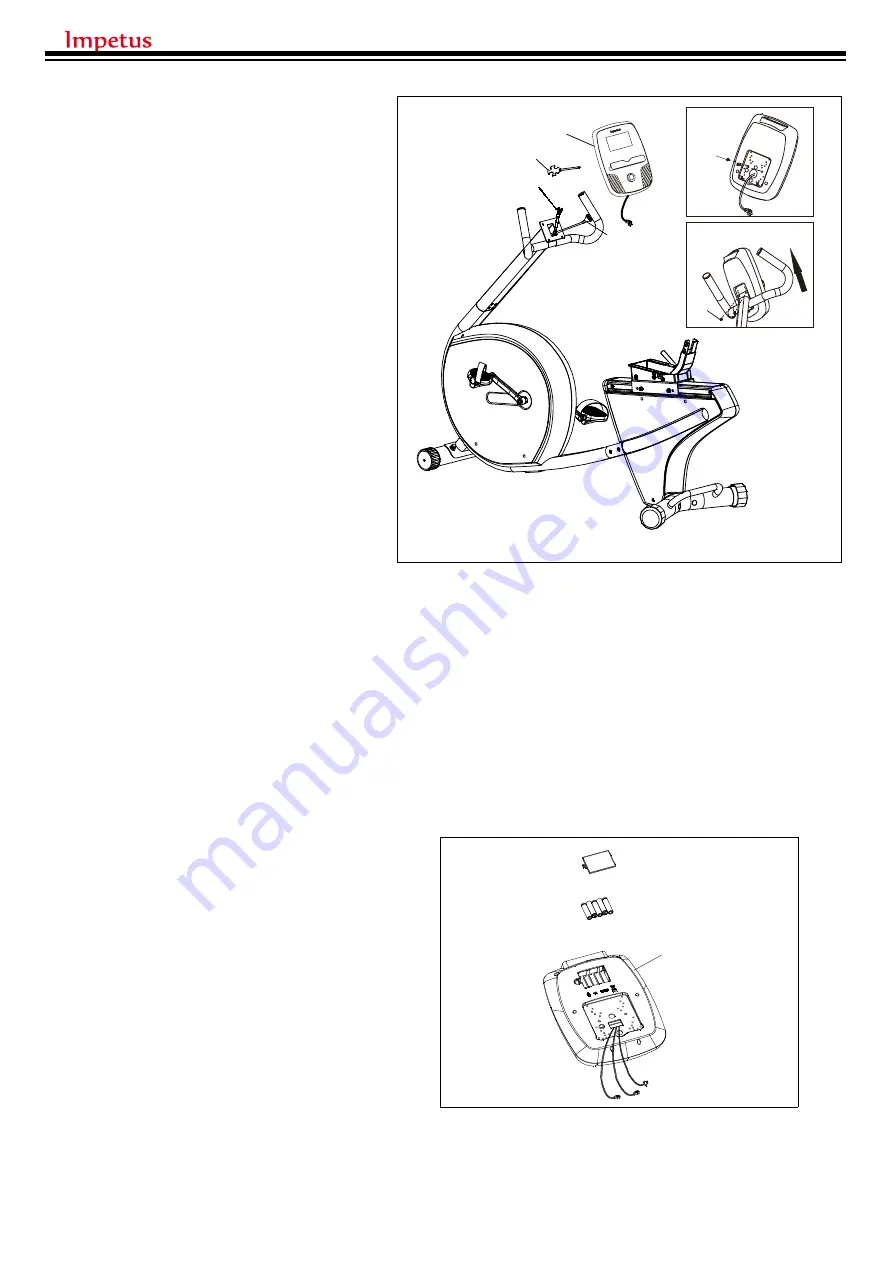
(1) Attach  the  computer  (48)  to 

the  front  tube  by  using  Screw 
driver  (103)  to  loose  the  4 
Philip screws (49) on back side 
of computer . Be sure only take 
out  the  2  screws  on  top  the 
bottom 2 screws only need half 
loose as (Fig. 7-1).

(2) Connect  the  computer  upper 

wire (94) and hand pulse wire 
(95)  with  computer  (48).  Be 
sure  to  have  the  additional 
wire  get  into  the  tubing  first  , 
then  follow  the  (Fig.  7-2) 
attach and slide the computer 
to  the  computer  fixing  plate. 
Lock  the  bottom  2  screws 
first,  then  the  top  2  screws.   
When  moving  the  computer 
on fixing plate, make sure the 
bottom  2  screws  should  get 
into the 2 slot on fixing plate.

STEP 7-3

Insert 5 batteries into the


CONSOLE(#A1) 

as the graph 

shown

48

94

103

95

7-1

49

7-2

49

48

7

Summary of Contents for IR 500

Page 1: ...USER MANUAL...

Page 2: ...ANT INFORMATION ASSEMBLY INSTRUCTIONS SEAT ADJUSTMENT HOW TO ADJUST THE BALANCE OF THE TRAINER TELEMETRIC HEART RATE CHEST STRAP EXPLODED VIEW PART LIST WARM UP COOL DOWN CLEANING MAINTENANCE 3 5 11 1...

Page 3: ...3...

Page 4: ...4...

Page 5: ...pulse lower wire 88 in rear frame first then join the front frame A and Rear Frame C by 4 Allen screws to secure 2 on each side and Then put the Allen bolts 47 lock into the two holes on top of the fr...

Page 6: ...4 from the front tube 42 to the lower wire 96 of main frame and also connect the hand pulse wire 95 to the hand pulse lower wire 21 then insert the front tube 42 to the main frame A by 4 flat Allen bo...

Page 7: ...ire 94 and hand pulse wire 95 with computer 48 Be sure to have the additional wire get into the tubing first then follow the Fig 7 2 attach and slide the computer to the computer fixing plate Lock the...

Page 8: ...h Allen bolt 74 Arc Washer 104 and fasten the screws with Allen key 102 Connect the hand pulse wire of the handlebars 72 and 73 with the lower wire 88 of hand pulse STEP 9 Put the sliding seat support...

Page 9: ...e to be a line and then by 4 allen bolts 8 Allen key 102 to firmly tight STEP 11 Insert the back rest support J into the connector on Seat support of rear frame then by 4 Allen screws 47 4 flat washer...

Page 10: ...10 STEP 12 Fix the water bottle 105 rack onto the handlebar post with flat head screws 110 and fasten with open wrench with screw driver Tool 105 110...

Page 11: ...ition of the seat pull up the adjustment handle to loosen it Then move the seat forward or backward to the comfortable position and firmly push down the adjustment handle to tighten it BACKREST HEIGHT...

Page 12: ...A B HOW TO ADJUST THE BALANCE OF THE TRAINER Make sure the trainer is placed on the flat floor and rotate the leveling foot A B clockwise or counter clockwise so the leveling foot touches the floor 12...

Page 13: ...13...

Page 14: ...14...

Page 15: ...in cover right 1 82 Plastic sleeve 2 29 Crank L 1 83 Sliding tube 1 30 Crank R 1 84 Square cap 1 31 Flange nut M10 2 85 Philip Screw 4 32 Pedal L 1 86 Knob 1 33 Pedal R 1 87 Back rest 1 34 Hexagonal s...

Page 16: ...slightly slowly bend forward from the hips Allow your back and shoulders to relax as you stretch down toward your toes Go as far as you can and hold for 15 counts then relax Repeat three times Stretch...

Page 17: ...17...

Reviews: