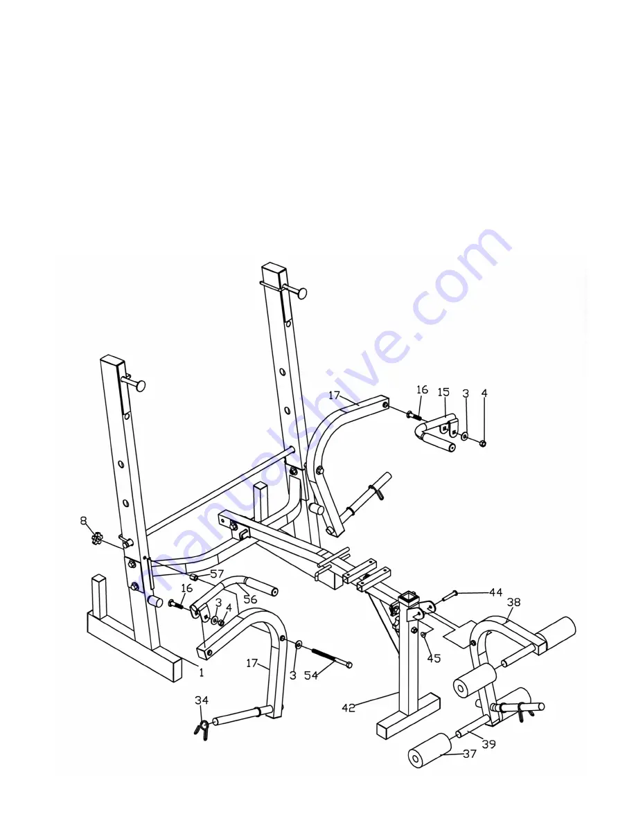
STEP 3
(SEE DIAGRAM 3)
A.) Attach a
∅
¾” Washer (#3) onto a M10 x 6 ¼” Hex Bolt (#54). Insert the Bolt through
the Butterfly (#17). Place a M10 Regular Nut (#57) onto the Bolt. Then insert the Bolt
through the hole on the Rear Upright Beam (#1). Secure the Bolt with a Lock Knob (#8)
behind the Upright Beam. Repeat the same step to install the other Butterfly.
B.) Attach the Right Butterfly Handle (#56) to the Right Butterfly (#17). Secure it with a M10
x 2 ½” Carriage Bolt (#16),
∅
¾” Washer (#3), and M10 Aircraft Nut (#4). Repeat the
same step to install the other side.
C.) Attach the Leg Developer (#38) onto the bracket on the Front Stabilizer (#42). Secure it
with a Hex Socket Axle (#44) and Hex Socket Screw (#45).
D.) Insert two Foam Roll Tubes (#39) halfway through the hole on the Leg Developer (#38).
Push four Foam Rolls (#37) onto the tube from both sides.
E.)
Place three Spring Clips (#34) onto the post on the Leg Developer and Butterfly.
DIAGRAM 3
6


