background image


Parts list 

KEY 

NO.  DESCRIPTION 


  Q’ty 


Canopy 

  1 

Support Tube End Cap 


Support 

Tube 

  6 

Cone-shaped Canopy Support End Cap 

Canopy Support Frame 


Lock 

Knob 

  1 

M6 Allen Screw 


Upper 

Frame 

  1 

Upper 

Cantilever 

  1 

10 

Right Connecting Tube 


11 

Left Connecting Tube 


12 

Ø ¾” Washer 


13 

Ø 5/8” Curved Washer 


14 

Ø 5/8” Lock Washer 


15 

M8 x ¾” Allen Bolt 


12 

16 

M10 x ¾” Allen Bolt 


12 

17 

Ø ¾” Lock Washer 


12 

18 

Ø ¾” Curved Washer 


19 

Cable 

  2 

20 

Ø 1 1/8” Cover Cap 


14 

21 

M12 x 4 ½” Allen Bolt 


22 

Ø 1” Washer 


23 

M12 Aircraft Nut 


24 

Main 

Post 

  1 

25 

Left Main Post Support 


26 

Right Main Post Support 


27 

Ø 5/8” Washer 


28 

Lower 

Cantilever 

  1 

29 

Bracket 

  1 

30 

Lounge Chair Support 


31 

M8 Aircraft Nut 


32 

Lounge Chair Side Frame 


33 

Lounge Chair End Frame 


34 

Nylon Sheet String 


35 

Nylon 

Sheet 

  1 

36 

Pillow 

  1 

37 

Pillow 

String 

  1 

38 

Ø 1” Hook End Cap 


39 

M12 Hook Lock Nut 


40 

Cantilever 

Hook 

  1 

41 

Upper Frame Hook 


42 

M6 x ½” Allen Bolt 


43 

Ø ½” Lock Washer 


44 

Ø 1” End Cap 


21 


Summary of Contents for Caribbean Lounge Chair GD-800

Page 1: ...Hardware Pack Assembly Instruction Parts List Warranty Ordering Parts Model GD 800 Retain This Manual for Reference 11 21 06 OWNER S MANUAL Caribbean Lounge Chair GD 800 IMPEX INC 14777 DON JULIAN RD CITY OF INDUSTRY CA 91746 Tel 800 999 8899 Fax 626 961 9966 www impex fitness com info impex fitness com ...

Page 2: ... machine As a manufacturer we are committed to provide you complete customer satisfaction If you have any questions or find there are missing or damaged parts we guarantee you complete satisfaction through direct assistance from our factory DO NOT RETURN THE UNIT TO THE STORE To avoid unnecessary delays please call our TOLL FREE customer service number Our Customer Service Agents will provide imme...

Page 3: ...n Lounge Chair at a time Care and Maintenance 1 Periodically inspect all parts Check all nuts and bolts twice monthly during the usage season for tightness and tighten as required It is particularly important that this procedure be followed at the beginning of each season 2 Replace any worn and damaged part immediately Check all coverings for bolts and sharp edges twice monthly during usage season...

Page 4: ...WARNING LABEL PLACEMENT 3 ...

Page 5: ... 12 16 M10 x Allen Bolt Qty 12 17 Ø Lock Washer Qty 12 18 Ø Curved Washer Qty 6 20 Ø 1 1 8 Cover Cap Qty 14 21 M12 x 4 Allen Bolt Qty 4 22 Ø1 Washer Qty 8 23 M12 Aircraft Nut Qty 4 27 Ø 5 8 Washer Qty 4 31 M8 Aircraft Nut Qty 4 42 M6 x Allen Bolt Qty 6 43 Ø Lock Washer Qty 6 Tools 4 Allen Wrench Qty 1 6 Allen Wrench Qty 1 8 Allen Wrench Qty 1 4 ...

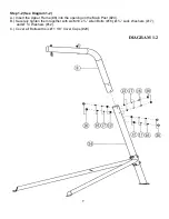
Page 6: ...chine to avoid possible injury STEP 1 1 See Diagram 1 1 A Attach the Left Right Main Post Support 25 26 to the Main Post 24 from each side B Align the holes and securely tighten them together with four M12 x 4 Allen Bolts 21 eight Ø 1 Washers 22 and four M12 Aircraft Nuts 23 C Cover all Bolts and Nuts with eight Ø 1 1 8 Cover Caps 20 See Note on next page DIAGRAM 1 1 5 ...

Page 7: ...Note When installed the Ø 1 Washer make sure the lip of the washer faces outside away from the frame The groove inside the Plastic Cover should clip onto the lip of the Washer 6 ...

Page 8: ... A Insert the Upper Frame 8 into the opening on the Main Post 24 B Securely tighten them together with six M10 x Allen Bolts 16 Ø Lock Washers 17 and Ø Washers 12 C Cover all Bolts with six Ø 1 1 8 Cover Caps 20 DIAGRAM 1 2 7 ...

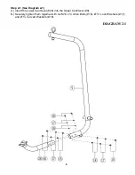
Page 9: ...tep 2 1 See Diagram 2 1 A Insert the Lower Cantilever 28 into the Upper Cantilever 9 B Securely tighten them together with six M10 x Allen Bolts 16 Ø Lock Washers 17 and Ø Curved Washers 18 DIAGRAM 2 1 8 ...

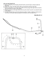
Page 10: ...leeve on the Nylon Sheet 35 onto the Lounge Chair Side Frame and all the way up to position A shown in the diagram D Slide the left sleeve on the Nylon Sheet onto the Left Connect Tube 11 to position B shown in the diagram E Pull back the right sleeve on the Nylon Sheet to position C shown in diagram Make sure the rivet holes on the Nylon Sheet are parallel to the Right Left Connecting Tubes DIAGR...

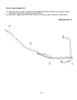
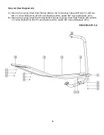
Page 11: ... Insert the other Lounge Chair Side Frame 32 through the left sleeve on the Nylon Sheet 35 all the way into the Left Connect Tube 11 B Insert the Lounge Chair End Frame 33 into the two Lounge Chair Side Frames 32 DIAGRAM 2 3 10 ...

Page 12: ...Connecting Tubes 10 and 11 with two M8 x Allen Bolts 15 Ø 5 8 Lock Washers 14 and Ø 5 8 Curved Washers 13 B Secure the Lounge Chair End Frame 33 to the two Lounge Chair Side Frames with two M8 x Allen Bolts 15 Ø 5 8 Lock Washers 14 and Ø 5 8 Curved Washers 13 DIAGRAM 2 4 11 ...

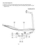
Page 13: ...p 2 5 See Diagram 2 5 A Attach the Lounge Chair Support 30 to the two Lounge Chair Side Frames 32 B Secure it with four M8 x Allen Bolts 15 Ø 5 8 Lock Washers 14 and Ø 5 8 Curved Washers 13 DIAGRAM 2 5 12 ...

Page 14: ...Diagram 2 6 A Attach the Lounge Chair Support 30 onto the bracket on the Lower Cantilever 28 B Secure it with four M8 x Allen Bolts 15 one Bracket 29 four Ø 5 8 Washers 27 and four M8 Aircraft Nuts 31 DIAGRAM 2 6 13 ...

Page 15: ...are in diagonal direction to each other into the holes on the Canopy Support Frame 5 B Secure each Support Tube with one M6 x Allen Bolt 42 and Ø Lock Washer 43 C Insert the other two Tubes into the Canopy Support Frame 35 without tightening them DIAGRAM 3 1 14 ...

Page 16: ...Step 3 2 See Diagram 3 2 A Insert the end of the Tubes 3 into the pockets on the Canopy 1 DIAGRAM 3 2 15 ...

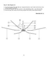
Page 17: ... 3 3 A Push out the two Support Tubes 3 that were not tightened in step 3 2 above away from the center B Secure each Support Tube to the Canopy Support Frame with one M6 x Allen Bolt 42 and Ø Lock Washer 43 DIAGRAM 3 3 16 ...

Page 18: ...Step 4 1 See Diagram 4 1 A Hang the Cantilever Hook 40 onto the Upper Frame Hook 41 B Attach two Cables 19 to the hook underneath the Upper Cantilever 9 DIAGRAM 4 1 17 ...

Page 19: ...cure it with the Velcro strap C Insert the tube on the Canopy Support Frame 5 into the pivot on the Upper Frame 8 Secure it with a Lock Knob 6 D To adjust the Canopy position loosen and pull the Lock Knob Then turn the Canopy Support Frame to obtain the desired position E Attach the other end of the two Cables 19 to the hooks on the Left Right Main Post Support 25 26 to lock the Lounge Chair when ...

Page 20: ...ction of the bed with both hands holding onto the bed frames DO NOT sit on the edge or the end of the bed That would cause the bed to tilt over and cause injury 3 When you first sit on the bed the bed will rock back and forth That is normal It takes a little time to get used to the motion 4 Only lay on the bed with your head on the pillow 5 The Canopy can be swing away by simply turn and pull the ...

Page 21: ...EXPLODED DIAGRAM 20 ...

Page 22: ...7 Ø Lock Washer 12 18 Ø Curved Washer 6 19 Cable 2 20 Ø 1 1 8 Cover Cap 14 21 M12 x 4 Allen Bolt 4 22 Ø 1 Washer 8 23 M12 Aircraft Nut 4 24 Main Post 1 25 Left Main Post Support 1 26 Right Main Post Support 1 27 Ø 5 8 Washer 4 28 Lower Cantilever 1 29 Bracket 1 30 Lounge Chair Support 1 31 M8 Aircraft Nut 4 32 Lounge Chair Side Frame 2 33 Lounge Chair End Frame 1 34 Nylon Sheet String 1 35 Nylon S...

Page 23: ...ther damages with respect to any economic loss loss of property loss of revenues or profits loss of enjoyments or use costs of removal installation or other consequential damages or whatsoever natures Some states do not allow the exclusion or limitation of incidental or consequential damages Accordingly the above limitation may not apply to you The warranty extended hereunder is in lieu of any and...

Reviews: