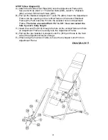
STEP 3 (See Diagram 3)
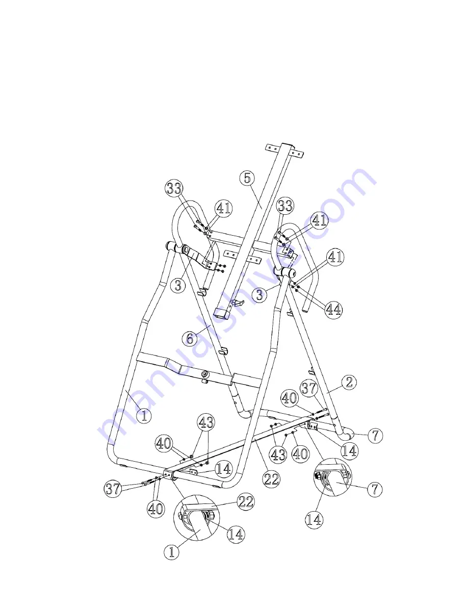
A.) Place the Backrest Frame (#5) onto the two Pivot Frames (#3). Secure it to each Pivot
Frames with two M8 x 2 1/8” Allen Bolts (#33), four Ø 5/8” Washers (#41), and two M8
Aircraft Nuts (#44).
B.) Attach the Stabilize Belt (#22) to the Rear Base (#7) and the base of Front Support
(#1). Place a Belt Bracket (#14) in between the Belt and the base. Secure the Belt to
each base with two M6 x 1 7/8” Allen Bolts (#37), four Ø ½” Washers (#40), one Belt
Bracket (#14), and two M6 Aircraft Nuts (#43).
C.)
Securely tighten all Nuts and Bolts in Step-1, Step-2, and Step-3.
DIAGRAM
3
7
Summary of Contents for MARCY IVT-600
Page 5: ...4 ...
Page 12: ...EXPLODED DIAGRAM 11 ...


