PAGE 19
6
ø 6
mm
f
e
PN80499
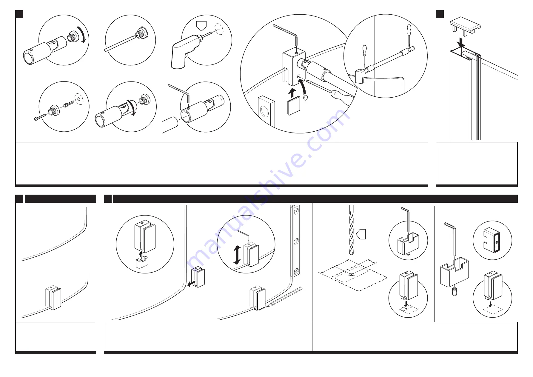
Remove the tie bar assembly from the panel.
a:
Unscrew the wall bracket from the end of the tie bar bracket.
b:
Place the wall bracket in the marked position and mark the fixing hole onto the wall.
c:
Drill the position marked using a 6mm drill bit, 30mm deep.
d:
Insert the wall plug and fix the wall bracket to the wall using a 32mm screw and washer.
Note:
The screws and wall plugs supplied are for masonry walls. For lightweight walls i.e. stud
partitions, plasterboard etc, use the correct type of fixings.
e:
Screw the tie bar bracket back onto the wall bracket.
f:
Reposition the tie bar into the tie bar bracket and the other end (with top panel bracket fitted) onto the panel
(with grub screw on the inside). Tighten the tie bar bracket grub screw onto the tie bar.
g:
From inside, slide the spacer plate (PN80573 50) up between the bracket and glass panel, tighten the grub
screw (
1
) onto the panel.
Ensure the panel is vertical and tighten the grub screw in the top of the bracket onto
the tie bar (
2
). Push fit the screw cover cap. Tighten the large screws on both tie bar brackets.
7
Push fit the top cap onto the top of the
wall channel.
32
mm
a
1
2
c
d
g
Inside
b
3mm
2mm
8
Foot Options
Option A:
Without foot - follow
step 10.
Option B:
With foot - follow
step 9.
A
B
9
Option B -
With foot
a
a:
Use the 3mm allen key to wind-up the pin on the inner foot
*
so it is
flush with the underside. Place the inner
foot into the foot.
Position the assembled foot under the panel as far as it will go without lifting the panel off the
floor.
b:
Ensure the panel is vertical and if required adjust the foot to level the panel. Mark the position of the foot
onto the floor (all the way around).
Remove the foot and the panel.
b
*
3mm
a
Option a:
Drilling floor for foot
- Use the dimensions above to mark and drill the ‘pin’ hole in the floor. Using
a 4mm drill bit, carefully drill a shallow hole (no deeper than half the thickness of the tile etc.). Use the allen key
to adjust the ‘pin’ in the inner foot
*
to fit into the hole. Position the assembled foot in the marked position.
Option b:
Sealing foot to floor
- Use the allen key to remove the ‘pin’ from the inner foot
*
. Apply silicone
sealant to the underside of the inner foot. Position the assembled foot in the marked position.
b
17
mm
17
mm
8
mm
ø 4
mm
*
2mm
2mm
*
PN80573 50


