Speedway Reader IPJ-R1000 for UHF Gen 2 RFID
9
Table 2-3 GPIO Interface Electrical Specifications
Pin
Parameter
Description
Minimum
Maximum
Unit
Conditions
GPIN[3:0]
V
IH
HIGH-level
input
voltage
2 5
V
GPIN[3:0]
V
IL
LOW-level
input
voltage
0 0.8
V
GPIN[3:0]
I
LI
Input
Leakage
Current
-5 5
µA
V
in
=0–5V
GPIN[3:0]
V
I
Input
Voltage
Range
-5 5 V
No
damage
GPOUT[7:0] V
OH
HIGH-level
output
voltage
3 3.3
V
I
out
= 100 µA
GPOUT[7:0] V
OL
LOW-level
output
voltage
0 0.25
V
I
out
= -100 µA
GPOUT[7:0] V
I
Input
voltage
range
-5 5 V
No
damage
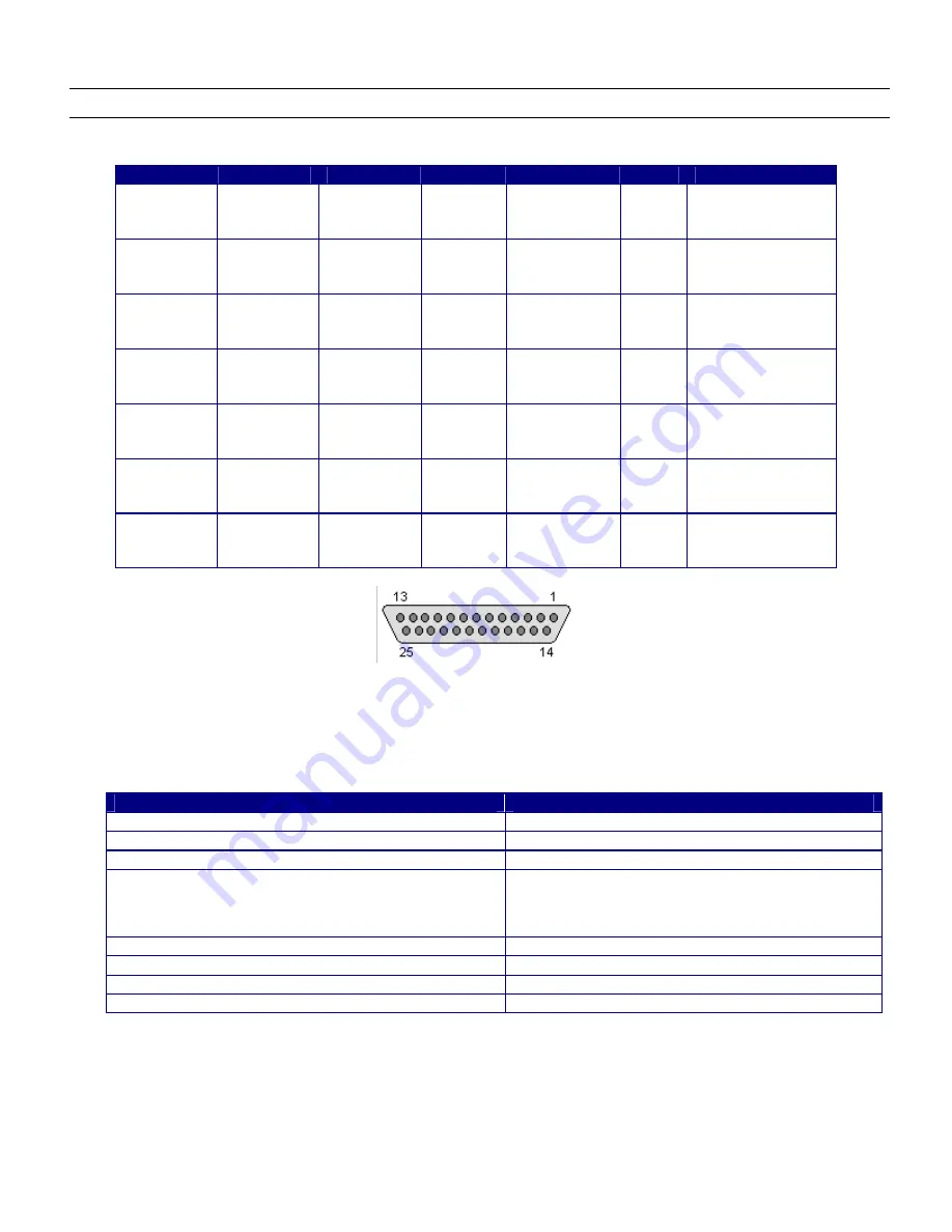
Figure 2-2 DB-25 Female Connector
The labeled LEDs indicate
Power
,
Status
, and antenna activity. The LEDs that correspond to the connected antenna(s)
(labeled
1
,
2
,
3
, and
4),
only light green when active (transmitting). A description of the status LED states appears in Table 2-4.
Table 2-4 LED Status Indicators
Reader Operation
LED Action
Startup Continuous
Red
Power-on Start Test (POST) Failure
Flashing Red (~2 Hz)
Bootloader Running
Off
File System Mounting Operation
(May also occur in certain upgrade scenarios to indicate the
unit is functional but in a file system operation that will take
some time to complete.)
Alternately Flashing Red/Green (1 Hz)
Speedway Reader able to Accept Mach1™ Connection Continuous Green
Speedway Reader in Active Mach1™ Connection
Flashing Green (1 Hz)
Inventory in Progress with Tags in Field
Flashing Orange (1 Hz)
Inventory in Progress with no Tags in Field (for 3 sec)
Flashing Orange (1/3 Hz)
Note
Mach1™ denotes the Speedway RFID Command Interface, used by the reader to communicate with
EPCglobal™ Generation 2 (Gen 2) RFID tags.
2.3. Mounting the Speedway Reader
When securing the unit with #10 screws via the four mounting holes, the Speedway reader may be mounted horizontally or


